
FreeCAD is a powerful software, which fits a wide range of simple to extremely advanced use-cases. Today, for the last post in this series, we’ll learn about one of these more advanced concepts : making configurable parts which automatically update based on some property or configuration. While slightly more complex to set up, these features offer a whole world of interesting possibilities to create reusable parts and useful projects. Buckle up !
Expressions
Almost every time we do something in a CAD software, we are asked to type some value or dimension. Whether it is the diameter of a circle in a sketch, the length of an extrusion, the radius of a fillet, the number of entities in a repetition function, or the angular offset of an attachment, these are all values that we need to give to FreeCAD for it to compute the part that we want.
However, sometimes, those values and dimensions only make sense relative to each other. For instance, what if, in a sketch, the width of some rectangle should always be 2.5 times its height for our part to be on spec? And also, the length of the pad operation applied to this sketch should always be half the height of the rectangle? If we update the height of the rectangle, we could edit all the other dimensions, calculate them manually according to the requirements of our part, and update them one by one — but that wouldn’t be very reliable, and it goes against the very principle of parametric design.
What we want instead, is to express these requirements directly in the design of the model, and let the software automatically calculate and update everything for us as needed. For this, we need expressions.
Binding dimensions to each other
Expressions are a staple of CAD software, so you may already be familiar with them. However, where FreeCAD shines, even compared to expensive alternatives, is that almost every value can be mapped to an expression.
Just to bring the point home, here is a convoluted example : in a Pad feature object, the base sketch that this operation is based upon is a property of this object — and since every property can be mapped to an expression, that means that we can write an expression that points to a specific sketches among several, therefore completely customize the resulting shape, according to some arbitrary conditions and parameters of our choice. How about that?
But that was just a foretaste to illustrate of how powerful expressions can be — for now let’s get back to our simpler example with the rectangle. We’ll start with a new document, then create a Part, a Body, and a Sketch on the XY plane, then draw a rectangle with a 10mm height centered on the origin (with G V) :
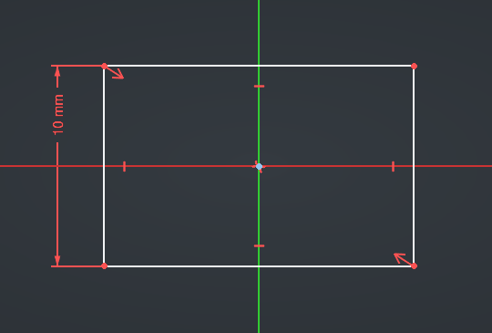
How do we specify our requirement that the width should be 2.5 times the height?
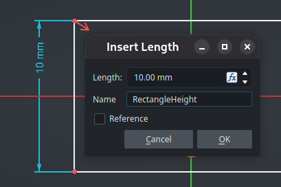
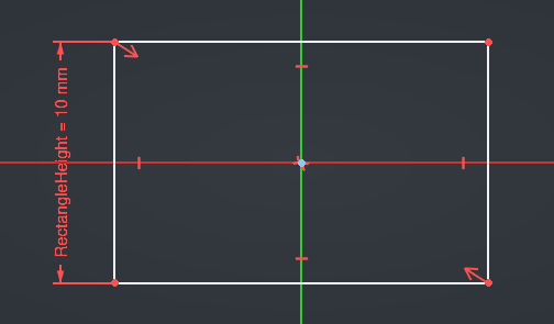
First, to make things easier, we need to give a name to the reference dimension (the height). Double-click on it and specify its name, for example “RectangleHeight” :
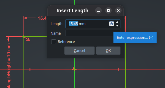
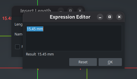
Now, add an horizontal dimension on the line at the top, then either click on the Fx icon at the right of the Length value or simply type “=” to open the Expression Editor :
Expressions in FreeCAD are powerful and can contain a lot of different things : references to properties of other objects (like a named dimension in a sketch or the length of a previous pad operation), mathematical operators (like additions or divisions), mathematical functions (line sin() or abs()), conditional statements, vectors, references to objects in the current document or other documents, … Expressions are also unit-aware : if you add a value in millimeters to a value in meters, FreeCAD will calculate it correctly. If you want to learn more about everything you can do with expressions, take a look at the wiki.
Here, we need to write an expression for the width dimension that references the height dimension and multiplies it by 2.5. Dimensions are a kind of constraint, and constraints are grouped in the Constraints property of our current sketch. Inside this property, we can access a constraint either by its internal name, or more easily by the custom name we have given it. And since we are inside the sketch, we can access its properties directly without naming the sketch object explicitely. We can therefore write this expression :
2.5 * Constraints.RectangleHeight
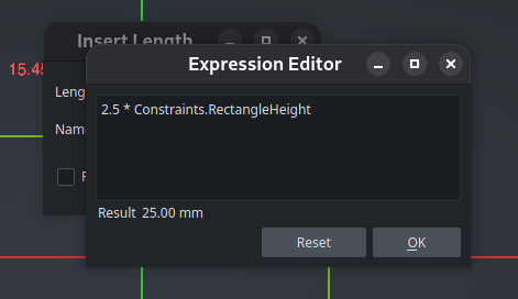
While typing, FreeCAD provides a helpful autocomplete feature, which makes it easier to discover which properties and names are available. Also, it automatically calculates the resulting value in real-time and displays it under the expression. Neat !
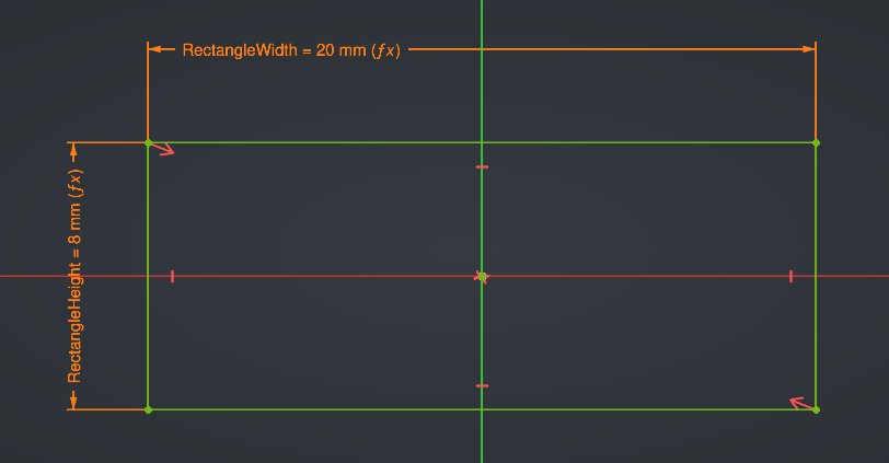
Validate the expression, then give the name “RectangleWidth” to this dimension and validate. The dimension now appears in orange with an “(fx)” suffix to indicate that it is piloted by an expression :
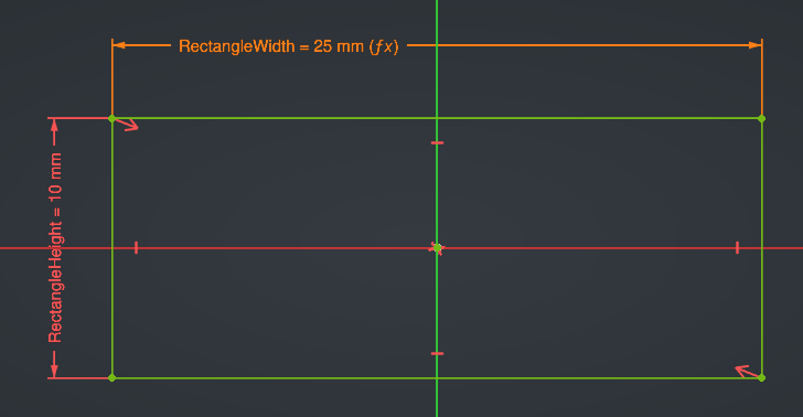
Try changing the value of the height dimension, and see how the width dimensions is automatically recalculated.
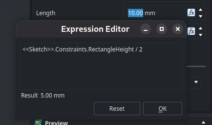
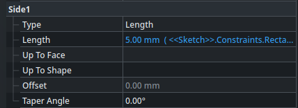
We can now close the sketch, then create a Pad operation whose Length property is (as specified by the arbitrary requirement that we decided earlier), half the height of the rectangle. This works exactly the same way, by typing “=” while the cursor is on the Length input (or clicking on the Fx icon). The only difference is that, since we are now outside the sketch (we are in the context of the Pad object), we need to reference it explicitly in order to access its constraints. Here is the expression we need :
<<Sketch>>.Constraints.RectangleHeight / 2
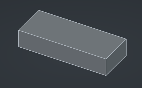
This is great : now, if we go back to the sketch and change the width of the rectangle, all the other dimensions of the volume will be updated accordingly in a parametric way. Using expressions this way on properties allows all kind of advanced possibilities for complex models.
However, you may wonder, what about those angle brackets around Sketch ? The reason is simple. As we saw in a previous posts, objects have both an internal name and a label, each of them unique inside the document — and we can use one or the other to reference the sketch object in an expression. An internal name can be referenced directly, while a label has to be written inside angle brackets << >>.
The reason for this special marker to exist is that behind the curtain, FreeCAD will actually translate that label to the internal name of the corresponding object. If you go to the Tree View and press F2 to rename the
Sketchobject (i.e. change its label) toSketch2for instance, you might expect the expression to break. Instead, if you edit the Pad and open the expression, you will see that it now says<<Sketch2>>: the expression was automatically updated with the new label. Using angle brackets therefore gives the best of both world : you can use descriptive names in your expressions, while still ensuring they are robust against the renaming of the referenced objects later.
Custom properties
As we said earlier, every property of an object can be mapped to an expression (even its Label, if you need that for whatever reason — that will update the name of the object displayed in the Tree View parametrically). After selecting an object, in the Property View, right-click on any property and choose Expression from the contextual menu to open the Expression Editor for this property. Afterwards, the value will be displayed in blue, like it already is for the Length property of our Pad operation :
Another thing that we quickly glossed over in a previous post that we can take advantage of here, is the fact that we can add custom, arbitrary properties on an object. As everything else, these custom properties can be referenced in expressions (as well as be mapped to an expression themselves of course, though that’s not the point here). Right now, all the dimensions of our part are automatically recomputed if we change the width of its base rectangle, but let’s say that we have to do that often and we find it too cumbersome to have to edit the sketch every time. We can add a custom property on the sketch object, then reference it as an expression inside the RectangleHeight dimension in the sketch itself.
Let’s do this. Select the sketch in the Tree View, then right click anywhere in its Property View and select Add Property from the contextual menu. In the dialog, set the name to “BaseWidth“, the group to “Configuration” (it doesn’t exist in the list, but we can type it directly, it will be automatically created), and the type to “App::PropertyLength” (since this property represents a dimension). Let’s also set the default value to 8.0 mm for example, and we can also chose a tooltip to describe the purpose of this property if we want.
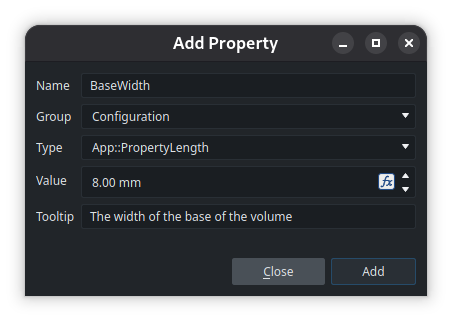
When you click Add the dialog stays open to let you add multiple properties quickly, but for now we can close it. The new property and group appear in the Property View of the sketch :
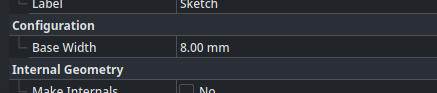
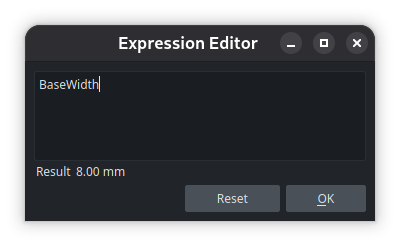
Now, edit the sketch, then edit the RectangleHeight dimension. Assign an expression to it by pressing =, that simply contains BaseWidth. Since we are inside the sketch, and the property is applied on the sketch itself, we are already in the right context — no need to prefix anything. You’ll see the dimension turn orange, and everything will be recomputed according to the new dimension of 8mm specified in the object’s property.
After closing the sketch, try updating the property and watch the change reverberate to all the dimensions of the cube.
It would make more sense to add the property to the Part object instead of the sketch, so as to provide a kind of “interface” to customize the part from the outside without digging deep into its children tree. However, there’s a hitch : if you tried to do this, FreeCAD would warn you about a cyclic dependency. This makes sense, because the Part object depends indirectly on the Sketch object (through the Body and the Pad), so in the general sense, the Sketch cannot depend on the Part at the same time. The issue here is that FreeCAD calculates the dependency graph at the objects level, not at the granularity of each individual property.
There are two solutions to break that cyclic dependency and work around this issue :
- either add our custom property on a dedicated object independent of the Part, such as a VarSet which we will cover just after this;
- or tell FreeCAD, in the expression that drives the dimension in the sketch, to use the value of the property without registering it as a dependency, by passing the reference into the
href()function like this : “href(<<Part>>.CubeBaseWidth)“. However, use this with caution, as it may have unintended side-effects — such as the model not recomputing automatically in some cases because of that dependency being hidden. I would recommend that you only usehref()if you have no other choice and you know what you are doing.Configuration tables, which we will also cover later in this post, are another way to achieve similar results (though a bit differently).
Read more about expressions on the wiki
VarSets
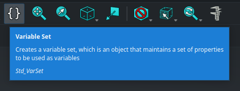
A VarSet is a simple object whose sole purpose is to contain properties (which you could also call variables, they are synonymous here) that can be referenced from expressions in other objects. It groups a set of variables, hence its name.
Add a VarSet using the last button it the core toolbar :
We have now learned about all the core tools available in FreeCAD ! Told ya’ that this toolbar wouldn’t have any secret for us at the end of this series !
The VarSet is created inside the active Part :
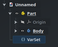
Since it’s not a “physical” object (it doesn’t have a shape and is not represented in the 3D view), it doesn’t have an eye icon. Furthermore, by default, its properties are very minimal : only a Label.
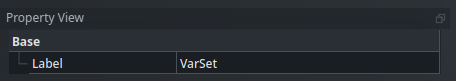
We can add a property named “CubeBaseWidth“, then edit the sketch and update the expression of the RectangleHeight dimension to :
<<VarSet>>.CubeBaseWidth
Again, the values of the properties of a VarSet can of course be mapped to expressions themselves, which gives almost infinite flexibility to express advanced constraints and behavior on your model.
If you have a more complex part with lots of sketches and features that depend on multiple parameters that you want to update easily, VarSets are a good way to group these parameters in a single place, at the root of the part, where they are handy to access — and without the cyclic dependency issue that we saw earlier.
Read more about VarSets on the wiki
Configuration tables
FreeCAD offers another object that you can use to store data : spreadsheets. As you might expect, a spreadsheet looks like what you might find in LibreOffice Calc or Microsoft Excel, and has more advanced features than VarSets — although they are not as powerful as those dedicated software, obviously.
Spreadsheet objects are created through, you guessed it, the Spreadsheet workbench :
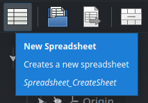
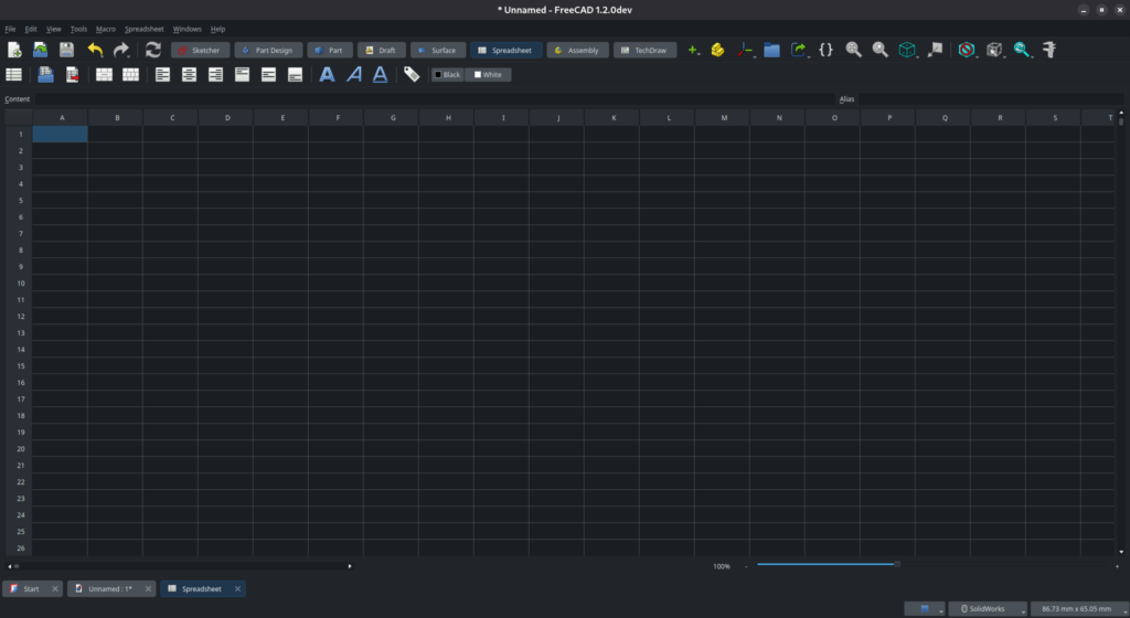
Spreadsheets don’t have any interesting property in their Property View. Instead, double-click on the spreadsheet object in the Tree View to open it in a new tab.
You can use spreadsheets in different ways, but for now we will mainly see one of their most interesting features : configuration tables.
Let’s say that our part exists in a few different variations — for instance, a screw available in a list of different lengths, or a battery socket which is available in a few sizes for standard battery types. As a simple example here, let’s say our box exists in sizes Small, Mid and Large. Also, we’ll add some markers in the corner of the part to identify its version when looking at it : the small will have only one marker, the mid will have two markers, and the large will have three.
We will set this up using a configuration table. A configuration table is a range of cells in a spreadsheet that defines a list of individual variants (as many as you need), as well as a set of variables (also as many as you need), with specific values for each variable and each variant.
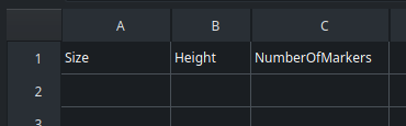
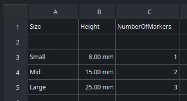
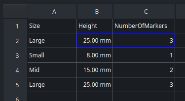
In the spreadsheet, we need to put the variants as rows, and the variables as columns. We start by adding a header — it’s just for us, to define what each column means. The first column will be the name of the size variant, the second column will be the height of the rectangle (which, after what we configured since the beginning of this post, drives all other dimensions through expressions), and the third will be the number of markers.
Next, we will define the list of variants in the first column. Leave the second row empty and start at the third row — you will understand why shortly. Finally, we specify some values for the variables for each available size. Spreadsheets, like properties and expressions, are unit-aware : “8” is not the same thing as “8 mm”. While not strictly mandatory, I recommend to always specify an explicit unit when entering dimensions in a spreadsheet. Otherwise, FreeCAD will try to determine the unit automatically, which may not be the one you intend.
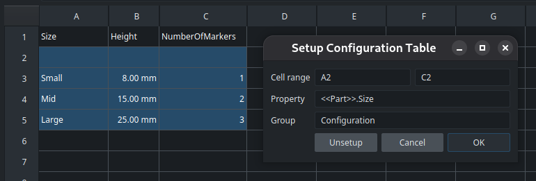
Once our table is complete, we need to convert it into a configuration table. Select the cells starting at the empty second row up to the end of the table, then right-click and chose Configuration Table from the contextual menu. In the options dialog that opens, in addition to the range of cells (which is automatically entered based on your selection), you will be asked for the name of a property : this is the property that will be created and linked to the table. The crucial thing to understand here is that if you specify an object, the property will be created directly on that object, which is a very useful feature. For instance, let’s tell the configuration table to create a “Size” property on our Part object (in a new group that we’ll call “Configuration“) :
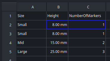
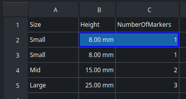
This will fill the second raw with a copy of the first variant by default, and materialize the variables of the configuration table with a blue border :
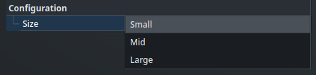
Now, if we go back to the tab of our main document and we take a look at the properties of the Part object, we will see that new property, with a value that can be chosen from the list of available variants using a drop-down menu :
Let’s set it to Large and go back to the spreadsheet. The second row of the table has been updated by the property, and the cells with the blue border reflect the values that should be used in our object for the selected configuration :
Only one last piece and our puzzle will be complete : how do we reference a cell in a spreadsheet from an expression in the main document?
The most direct way is with the coordinates of the cell. So for instance, the height value can be referenced as <<Spreadsheet>>.B2 — simple as that. But this is brittle though : if we modify the structure of the table, the expression will break.
The better way is to use an alias. An alias is a name given to particular cell in a Spreadsheet, which must be unique in the scope of that spreadsheet. To set an alias on the selected cell, either specify it in the Alias input box at the top right of the spreadsheet, or right-click on the cell, open its Properties panel, and go to the Alias tab. Here, we’ll set the aliases “Height” and “NumberOfMarkers” on the cells B2 and C2 respectively. Any cell which has an alias is shown with a blue background :
Now, we can edit the RectangleHeight dimension in our sketch with following expression :
<<Spreadsheet>>.Height
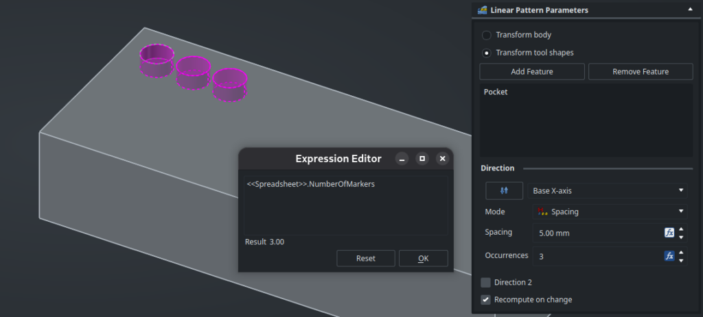
Finally, we can add a pocket feature on the current part, then a Linear Pattern function, and drive its number of occurrences with the NumberOfMarkers parameter from the spreadsheet :
Read more about configuration tables from the wiki
Our part is now fully and easily configurable. The Size property is exposed on the Part itself, and it drives all the internal features as needed. From the outside of the Part, we can select a variant without knowing anything about how the part has been built or how it works internally. Reasoning in terms of external interface and hiding the implementation details like this allows for to well-designed parts that can be easily distributed and reused in other projects.
If we want multiple instances of that same part with different sizes, remember the Link object with its Link Copy On Change property !
Spreadsheets have more use-cases than simple configuration tables. For instance, we could create a spreadsheet that summarizes some information about our model by relying on expressions that compute the data that we need (the total weight of the parts, the width of some sub-assembly, … anything we may imagine). The results can be exported as CSV, or they can feed some other specific process in other workbenches if needed.
Read more about spreadsheets on the wiki
Still not enough? We could go even one step further and create entirely custom objects scripted in Python, for almost unlimited possibilities of intricate behavior. That’s out of the scope of this article though, but take a look at the wiki if you want to learn more.
This last post concludes this (admittedly pretty thorough) “introduction” to FreeCAD. First of all, I would like to thank you for following this series — I hope that you learned a few things along the way, and above all, that I managed to convince you that FreeCAD is an incredible software with an actually very-manageable learning curve. We didn’t cover everything it has to offer — far from it, especially considering the wide range of available workbenches — but you now know more than enough to design advanced projects, and most importantly, you now have solid foundations to easily learn about the more specific topics that you need.
Thanks to workbenches, both official and third-party, FreeCAD offers a range of features unmatched by any other CAD package on the market. Here are a few pointers for your next project :
- Working on mechanical assemblies? You have better things to do than model standard screws or gears again and again, install the Fasteners and Gear workbenches instead.
- Using FreeCAD to create casings for your electronics projects? Sync your PCB with Kicad thanks to the KicadStepUp workbench, and use the Cables workbench to connect everything in a realistic way.
- Building or restoring a house? The official BIM (Building Information Modeling) workbench can create floor plans for you and supports standard IFC files. Draw your wires and pipes with the Cables and Dodo workbenches, and make your model more realistic with the ArchTextures workbench.
- Designing boats, airplanes, wings, propellers, or any kind of smooth and complicated shapes ? The Surface, Curves, Beltrami and AirPlaneDesign workbenches offer powerful tools in this area.
- Do you have a laser cutter ? The Sheet Metal and LCInterlocking workbenches will help you generate flattened boxes that you can directly import in your machine.
- On team CNC instead ? The official CAM workbench can calculate your toolpaths and export GCode through a range of post-processors.
- Is woodworking your thing? Make all kinds of furniture with ease thanks to the Woodworking workbench, and give them accurate materials using the database provided by the Woods workbench.
Find even more workbenches on the wiki, and feel free to share what you build on the forum.
So, what will you design first with FreeCAD ?