A pragmatic introduction to FreeCAD – part 6 : attachments
So, we are now experts at making all kinds of individual complex parts with FreeCAD. In today’s installment of this series, we’ll learn how to manipulate those parts in 3D space, and how to attach them to one another, in order to design models combining multiple parts.
There is another way to define the relative position of multiple parts : Assemblies. We will cover this topic in a future post. Attachments are still a good way to model a “fixed assembly” of parts (such as two panels of a casing with their set of screws), and are also used more broadly in FreeCAD as we’ll see toward the end of this post, so they are a useful tool to have in our toolbelt.
Placement
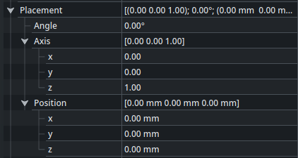
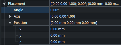
Every object which exists in the 3D view (such as sketches, bodies, parts, …) needs to be placed somewhere in space. This position and orientation is specified by the Placement property of that object. It’s a collapsible property available in the Data tab of the Property View, that looks like this :
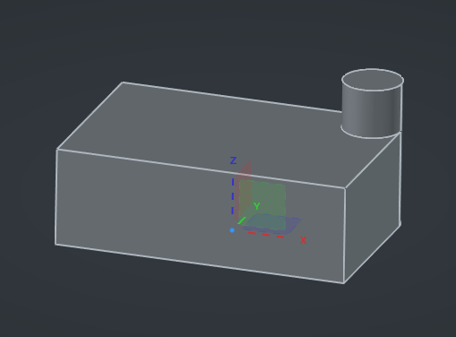
The Position property inside the Placement refer to the origin of the object. Part and Body objects (among others) have an explicit Origin object in the Tree View that can be made visible in the 3D view to help visualize around which reference the object is located in space. For example with the sample part that we designed in the last post, we can see that the origin is at the center of the bottom face :
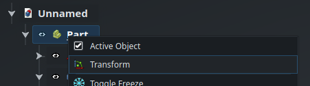
While we could edit the Placement property directly in order to move the part, there is fortunately an easier way. Right click on the Part in the Tree View then select Transform :
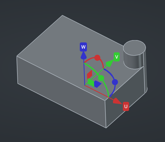
A 3D gizmo will appear in the main view, allowing you to translate and rotate the object easily :
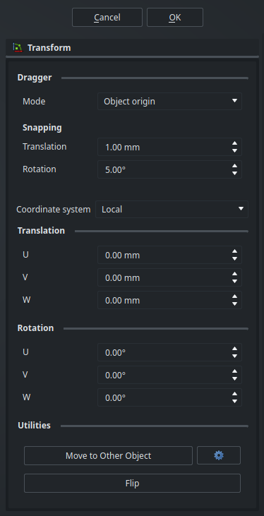
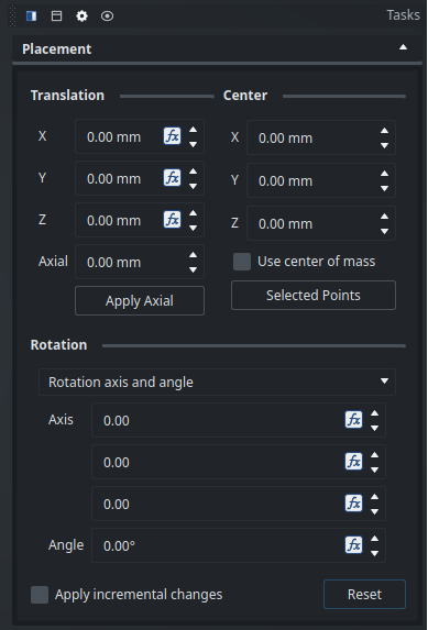
The Transform tool presents a few options in the Tasks panel :
When you are done, click Ok to validate the new position (and orientation), or Cancel to revert back to the original placement.
Since we have objects nested into one another (the Body is inside the Part), the Placement of the Body object is calculated relative to the Placement of its parent Part object : that way, if we move the Part, the Body (and every other object that the Part contains) will move with it, but the Placement property of the Body will not change. In the simple case of our current model, as long as the Origin objects are hidden, moving the Body or moving the Part may look similar in the 3D view (because there is no other object inside the Part), but this actually lead to different results. When working with complex models with lots of different parts, it’s very important to be aware of the origin of each object in order to have a robust and maintainable model.
Attachments
When designing a larger model with multiple parts working together, we usually want to position those parts relative to one another in a parametric way, so that their mechanical interfaces will always stay aligned even if we update the dimensions or position of some features of the parts.
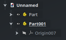
For example, lets say that there should be a second part in our model that should be fixed on top of the cylindrical feature of the first part. Start by creating a new Part object next to the first one, which will probably be called Part001 automatically :
Now, how do we make sure that the geometry inside Part001 (its inner Body object(s)) will always be fixed on top of the cylinder of Part, and will move if we change the dimensions of Part?
One way we could achieve that is by simply adding a Sub-Shape Binder in Part001 that references the top face of the cylinder of Part (like we learned last time), then building our geometry on top of it. That would work, but it would not be the best idea. Let’s think about it. First, the origin of this new part would still be located on the bottom face of the first part, completely separated from the shape of the part, which would not make much sense from the point of view of that part. Furthermore, if we updated the dimensions of the first part, the Binder would track the change of position of the face and everything in the second part would need to be recomputed — which should work, but would be inefficient. Also, that change would translate all the geometry of the second part inside its own local coordinate system because of some completely unrelated change in another part — again, not a very intentful dependency, and not a very sensible design.
Another way would be to use expressions in the values of the X, Y and Z properties of the Placement of the second part, that somehow calculates the correct position of the origin of the second part using references form the first part. This could work (and there might be cases where that would actually be a good solution), but it would be very cumbersome to set up in this case, and we haven’t yet learned about expressions anyway. Let’s find something else.
Fortunately, there is a better solution : Attachments. An Attachment is a kind of “module” that you can plug on an object (one which has a Placement property), and which will automatically control the Placement of that object based on some geometric constraints.
As I said earlier, there is a fourth way to place parts relative to one another : using an Assembly with Joints. This is especially handy when the parts should have some degrees of freedom respective to one another. We will look into the Assembly workbench in a future post — for now, we will assume that the two parts are simply fixed together, and that a simple Attachment is sufficient.
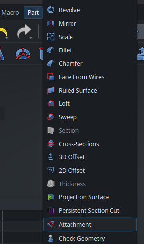
In order to add an Attachment to an object, select that object (in this case, Part001), then open the Part workbench (yes, not the Part Design workbench — its strange cousin), and look for the Attachment function at the bottom of the Part menu at the top of the screen :
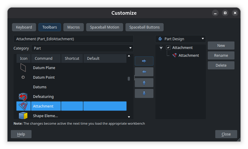
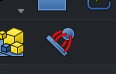
If you find yourself using attachments a lot, you can save yourself the trouble of switching workspace and digging into the menu every time by creating a custom button in the toolbar of the Part Design workbench. Right-click on an empty part of the toolbar, select Customize, then create a new toolbar (which I simply called “Attachment” here) and put the Attachment tool inside :
A new button will show up in the toolbar, that you can place anywhere you want :
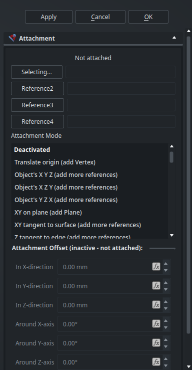
Selecting the Attachment tool will open the Attachment editor in the Tasks panel :
The Attachment editor in the Tasks panel.
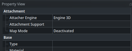
Also, you may notice that a new group of properties has appeared in our Part001 object :
Attachment properties in the Property View.
The Attachment editor works by selecting some geometry elements as references (up to four of them), then choosing an attachment mode. The available attachment modes depend on the number and types of geometry references currently selected. In any case, the goal is to define “something” that FreeCAD can use to calculate a location and orientation (i.e., a placement) for the origin of the current object. There is also the possibility to add an offset (in position or orientation) to the resulting placement.
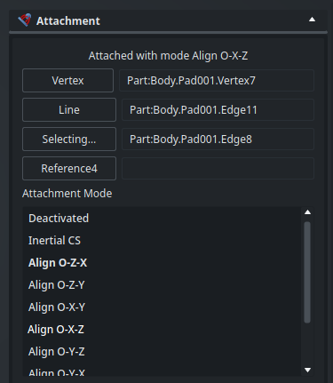
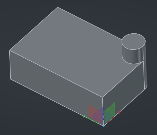
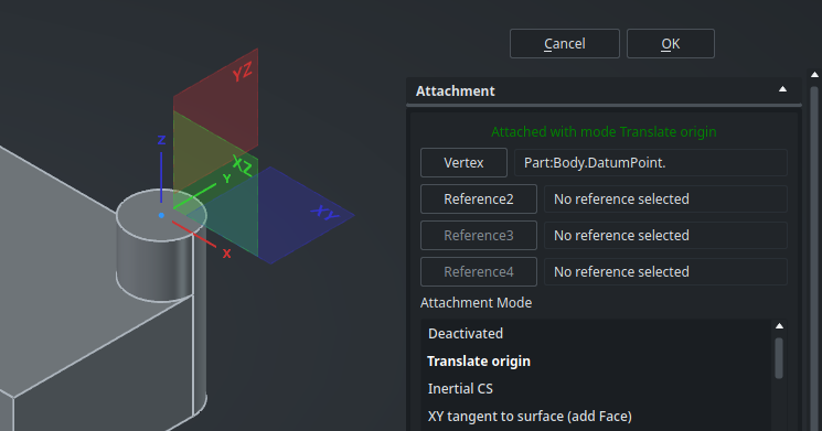
In order to grasp how this works, let’s make the origin of Part001 visible from the Tree View and try selecting reference elements. For example, lets select the closest bottom corner of the rectangle, then the adjacent edge that goes toward the right, then the other adjacent edge that goes toward the top. Among the available modes, we can select Align O-X-Z : this will move the coordinate system of Part001 such that its origin is on the corner selected as the first reference (“O” means the point), the X axis points to the second reference (toward the right), and the Z axis points to the third reference (toward the top). The Y axis is automatically calculated accordingly. Here is what it looks like in the Attachment editor (in the Tasks panel) and the 3D view :
An Align O-X-Z attachment based on a vertex and two edges.
The position of the new Part is automatically updated to track the selected references, as shown by its origin.
Sometimes, the coordinate system will follow the axes that you selected, but in the wrong direction. In case this happens, simply flip it by specifying a 180° offset around the appropriate axis at the bottom of the Attachment editor, or try checking the Flip sides option.
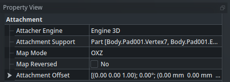
Validate this attachment. You will see the configured Attachment in the Property View :
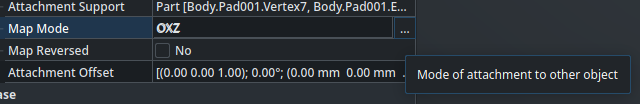
If you want to open the Attachment editor again to modify the attachment, click on the “...” button at the end of the Map Mode property :
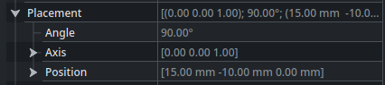
Interestingly, you can also see that the Placement property is now greyed-out and cannot be manually updated anymore : it is piloted by the Attachment, which has calculated the Position and Angle/Axis that satisfies the constraint of the configured attachment mode.
If we want to remove this attachment we need to set its Map Mode to Disabled, then manually reset the Placement of the object to 0/0/0.
Now that we understand how attachments work, let’s set up a more useful attachment for our parts on hand. First, disable the current test attachment of Part001 and reset its Placement, either by setting its Angle to 0° and its Position x, y and z to 0.00 mm in the Properties panel; or by right-clicking on the object in the Tree View, selecting Placement from the contextual menu, then clicking on Reset in the Task panel :
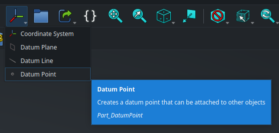
Since our requirement is that the second part should be fixed on the top face of the cylinder, it would probably make sense that the origin of that part is located in the center of that face. In order to help us set up this attachment, we will create a datum point at this location. Go back to the first body and make it active by double-clicking on it in the Tree View, then create a Datum Point using the toolbar :
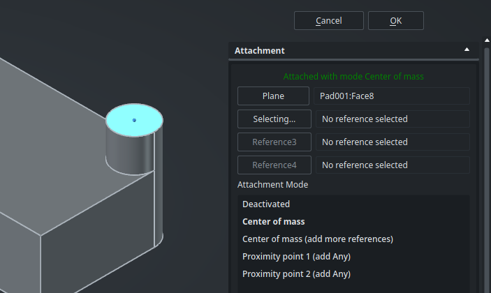
This will open, in fact… the attachment editor, again. This makes sense : by default, the point will be located in place using an attachment. Click on the top face of the cylinder : FreeCAD will automatically select the most useful attachment mode, Center of mass in this case, and place the point at the center of the face. Perfect !
Validate this attachment.
Now, come back to the second part and edit its attachment (from the Map Mode in the Property View). Click on Reference1 in order to have it show “Selecting…” then select the datum point that we just created (if you have trouble snapping to it in the 3D view, select it from the Tree View). Finally, select the Translate origin attachment mode if it is not already chosen automatically. This looks good, the origin of our part is now placed correctly :
By default, since we are just translating the origin, the orientation of the axes will stay the same as they were before. However, depending on what makes sense for that new part, we may want to reorient its coordinate system. The Translate origin attachment mode is, as its name implies, only a translation, so this attachment only drives the Position property of the Part, not its orientation. This means that in order to reorient the coordinate system, an attachment angular offset won’t work — instead we can directly rotate the part using the Transform tool.
Alright ! We can now add a Body in this part (which will be referenced to this new origin), and start designing it as usual.
Here, finding the center of the circle is pretty easy. However, sometimes when working with more complex geometries, it can be hard to attach a datum point like this exactly where needed using only attachment references and modes. An alternative solution is to use a Point primitive in a sketch : create a sketch on a relevant plane, add a Point primitive inside it (in normal mode, not in construction mode), use projected geometry and constraints from the Sketcher workbench to put that point at the correct place, and close the sketch. The attachment editor will be able to use that sketch point as a reference for the Translate origin mode as easily as a datum point.
As long as your parts do not have to dynamically move relative to one another like in a mechanism (you are designing a static thing with all parts fixed to each others), using Translate origin attachments like this between your Part objects is a simple and robust way to build complex models with lots of parts without relying on an assembly. It makes it easier to use cross-references of some geometry elements between parts (for instance, in order to make sure that two holes always stay aligned) since every part is design “in place”, while still ensuring a sensible origin for each part. The process will always be the same : after creating the main part of your model, for each subsequent new part you want to add to your model, create a point (datum or sketch) somewhere sensible around the mechanical interface between the two parts to use as the origin of the second part, then add a Body, model the part, and repeat.
When working with multiple parts, it is sometimes useful to display some of them as semi-transparent. This can be achieved using right-click > Toggle Transparency, or by selecting an object in the 3D view and pressing the shortcut V T (“view transparency”) on the keyboard.
Sketch attachments
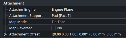
Attachments are a powerful feature which allow creating complex relationships between objects. And in fact, this is actually how sketches are positioned in space ! When you create a sketch and select a plane or face on which to draw it, it actually creates an attachment to this planar reference for the sketch object, with the attachment mode FlatFace (it also uses a different Attacher Engine, but that’s not important here). For instance, the second sketch of the first part (the one with the circle linked to the fillet) has this attachment linked to Face7 of the underlying Pad object :
Customizing the attachment of a sketch can be useful in some situations, for instance :
To add an offset to the sketch relative to its supporting plane, in order to shift the features that will be created from it.
To attach the origin of a profile sketch to the start point of a curve, for example when doing a Loft operation (it is easier and more robust to draw the profile sketch around its origin, than to bind or project the starting point of the curve on the sketch plane).
Understanding Attachments is a very useful skill that will allow you to create more robust and maintainable models. Feel free to keep experimenting with all the attachment modes and their specificities, they are documented on the wiki. Next time, we’ll look at another kind of useful object, Links, and we’ll also see how to change the appearance of our parts.