
Now that the core concepts of FreeCAD have no secret for us, let’s use them to actually design something !
“Part” vs “Part Design”
When discovering FreeCAD, it might be surprising to see that there is not one, but two different workbenches used to design 3D parts. To be fair, their generic names do not help clear up the initial confusion (something the developers are well-aware of and want to improve). However, there is actually a good reason to have these two different workbenches : they follow very different design philosophies, and depending on your background and your requirements, you will want to use one or the other for your project.
We will first take a quick look at the Part workbench, then dive deeper in the Part Design workbench.
Read more about the differences between Part and Part Design on the wiki
The Part workbench
The main idea when creating parts with this workbench is to create primitive geometric volumes (such as cubes, cylinders, spheres, or custom geometries extruded from a sketch), then combine them with boolean operations (unions, cuts, and intersections).


This is a style of modeling called Constructive Solid Geometry, or CSG, which is best visualized with this diagram from Wikipedia :

By Zottie through Wikipedia (CC BY-SA 3.0)
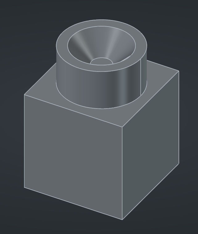
For example, a simple part containing three primitives and 2 boolean operations may look like this :
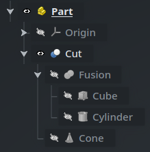
While easy to conceptualize for simple shapes, creating complex parametric parts this way can become challenging and hard to maintain, which is why this is not how the mainstream mechanical CAD packages work. We won’t use it in the rest of this series.
Read more about the Part workbench on the wiki
The Part Design workbench
Instead we’ll use the Part Design workbench, which works a lot more like the traditional CAD software that you may be used to, where 3D models are based on sketches and (additive or subtractive) features :

Read more about the Part Design workbench on the wiki
Bodies
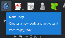
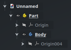
The base object we’ll use when working with the Part Design workbench is a Body, created by clicking on the blue staircase icon on the left. If you have created a Part object beforehand (and I recommend that you do), make sure it is active (that its name is in bold) : the new Body will be created inside the active Part, and will itself be made automatically active.
A Body is a special kind of container object that can only contain a specific subsets of objects, mainly sketches, features, and datum objects (construction geometry), and which enforces some specific behavior on them. The best way to learn about how this works is to start designing a simple part, so let’s scribble something.
Read more about the Body object on the wiki
Sketches
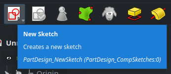
With the Body still active, create a new Sketch using the button in the toolbar of the Part Design workbench :
FreeCAD will ask you which of the base planes you want to draw the sketch on. Let’s select the XY plane, either from the 3D view, or from the Select Attachment tab in the Tasks panel on the right of the screen.
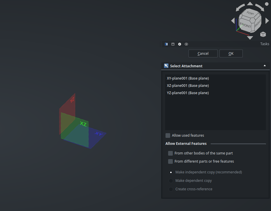
Actually, now is a perfect time to present the Task panel. When running a command, this contextual panel located below the 3D navigation cube on the right of the screen will ask for your input on how the command should perform (like it did just now by asking you for a base plane), and guide you regarding what you can do next. It’s a central element when working with the Part Design workbench (and others) and we’ll use it constantly from now on.
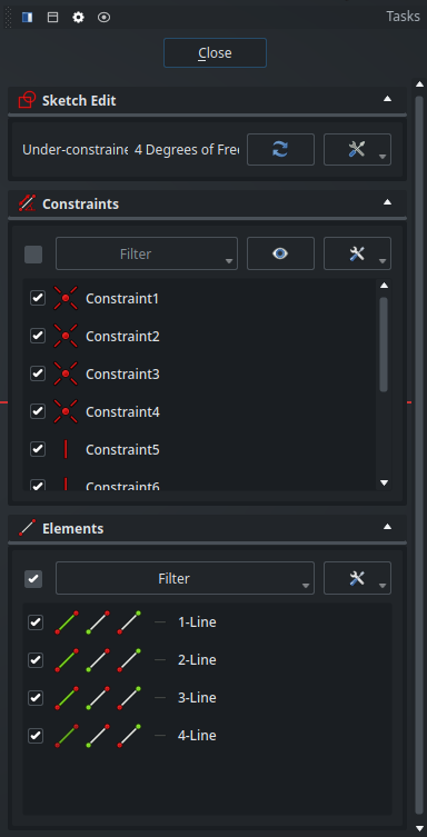
Once you have selected a plane, the view will move right above it, and the Task panel will show information about your sketch (which for now is empty) :
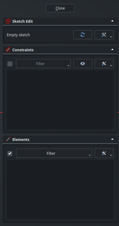
Also, you may have noticed that the UI automatically switched to the Sketcher workbench :

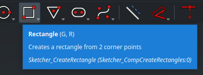
If you come from another CAD packages, the icons in this toolbar should feel familiar. We’ll take a deeper look at them in the next post — for now, simply select the Rectangle tool from the toolbar, then draw a random rectangle on the screen :
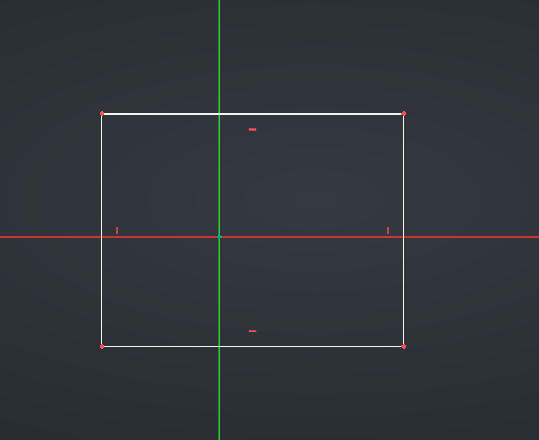
Use either right-click or the Esc keybinding to deselect the Rectangle tool, then click on the Close button at the top of the Tasks panel to close the sketch.
This will bring you back to the orthographic view and in the Part Design workbench.
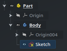
As expected, our new sketch is a child of the active Body :
We have created our sketch through the Part Design workbench. If you manually switch to the Sketcher workbench, you will also be able to create a sketch from there with a similar button in the toolbar. However, this technically works a bit differently, and creating a sketch this way will not bind it automatically to the active Body. When working with Part Design objects, make sure to create sketches from the Part Design toolbar.
Features
When the sketch is selected, FreeCAD will helpfully offer suggestions for your next action in the Tasks panel :
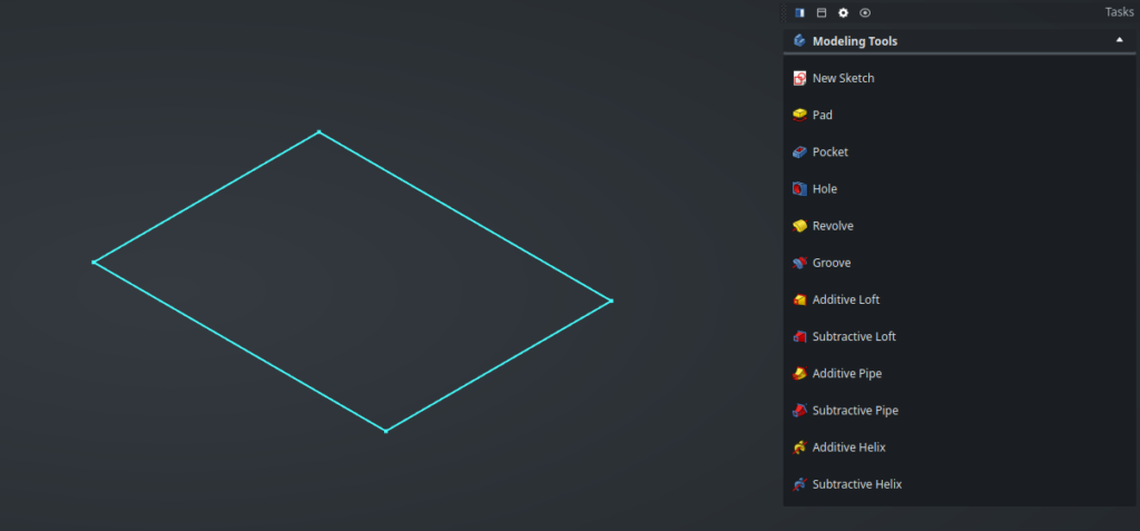
While the terminology might be different, you will probably recognize the Pad, Pocket, Revolve and other options offered here as the standard commands found in every 3D mechanical CAD software. The same commands are also available in the toolbar.
Here, we’ll use the Pad function to convert our 2D sketch into a 3D cube(-ish). As usual, the parameters for this command (most importantly in this case, the extrusion length) are available in the Task panel :
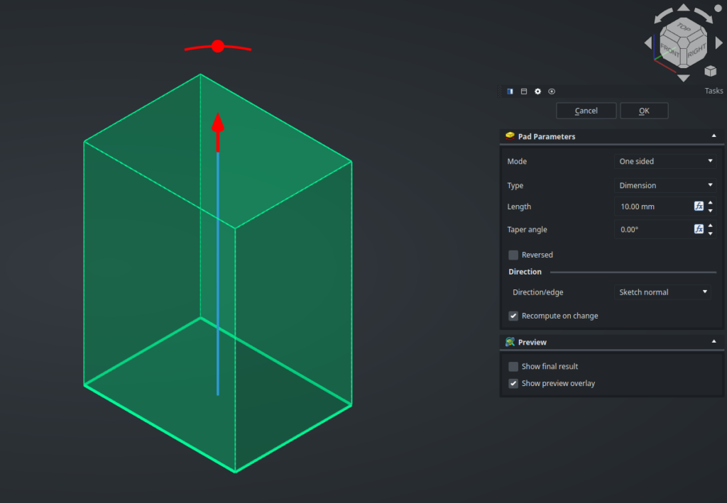
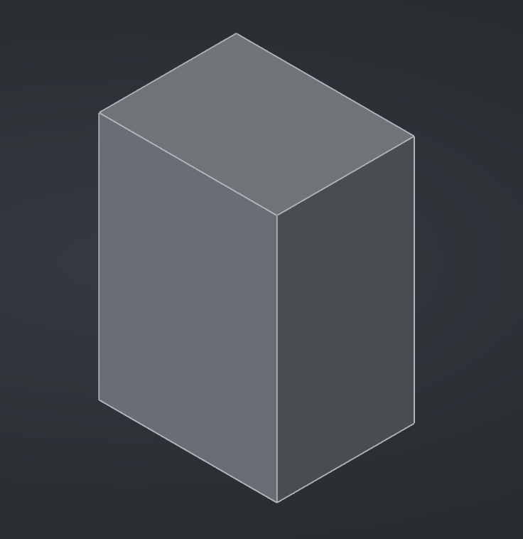
Keep the default values and validate. We now have a 3D volume, awesome !
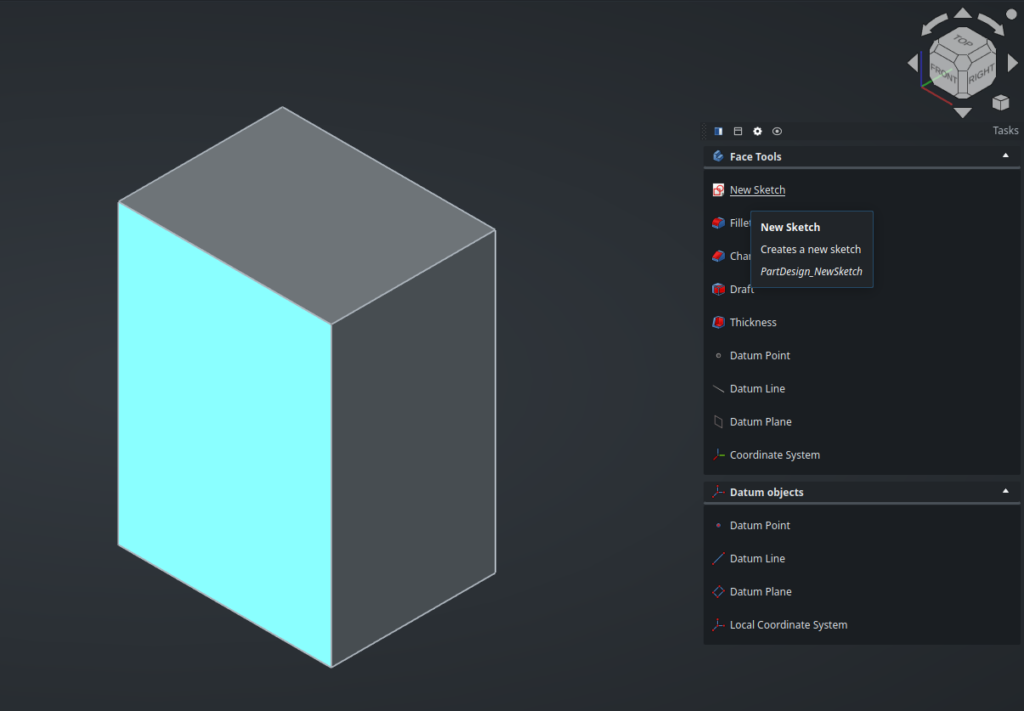
Now select the front face of this shape and start a new sketch on it :
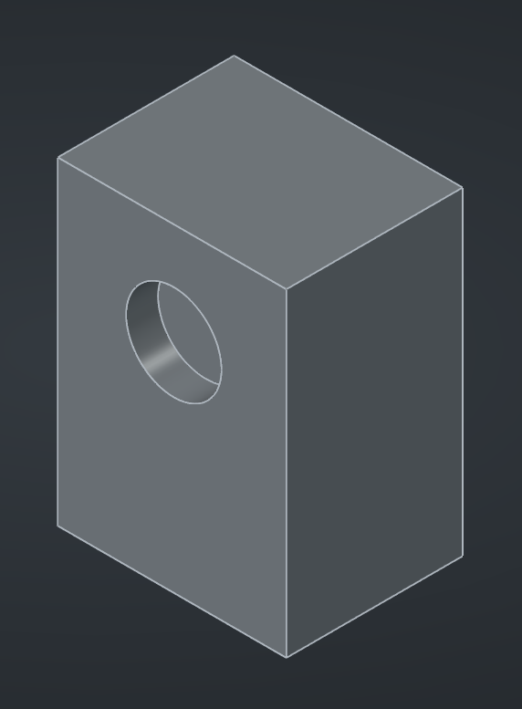
Draw something, close the sketch, then apply a function on it, exactly like we did before. Here, I’ve drawn a simple circle and used a Pocket operation with a shallow Length parameter to create a blind hole :
Timeline
After adding some other random operations, your Body in the Tree View may look something like this :
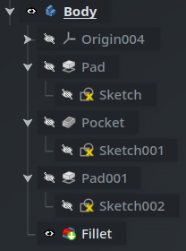
This might be a bit confusing at first, so let’s make sure we understand exactly what’s going on here.
When we create a Sketch object, it first gets added as a child of the current Body. Then, when we add a feature (such as a pad or pocket) with that Sketch selected, it creates a new feature object of the corresponding type (Pad or Pocket) as a child of the Body, and the Sketch is moved as a child of this feature.
When we add another feature (here, the Pocket object), it is added as a new child of the Body, and the first feature (the Pad object) is hidden (its eye icon is crossed out and its name turns grey). This is one of the special behaviors of the Body object type : it can contain features (features cannot exist outside a Body), but only one of them can be visible at a time. If you try to view the Pad again (by clicking on its eye icon, or by selecting it and pressing the space bar), the Pocket will automatically hide, and you will see the model without the pocket operation.
If you are familiar with the “timeline” in Fusion or the “feature manager” in SolidWorks, this might ring a bell. In FreeCAD, and more specifically in the Part Design workbench, a similar workflow is implemented through the special behavior of the Body object that contains a list of feature child objects. Each feature depends on the previous one and builds upon it by modifying its geometry to make a complex model step by step ; and we can move back and forth in that “model timeline” by seeing a single feature at a time in the tree, from top to bottom.
Editing features
Of course, this is a parametric model, so we can come back to any feature in the list if we want to modify it. Simply double-click on it in the Tree View : the visibility will automatically be set to the previous feature in the tree, and the Task panel will show you the parameters of that operation again. When you validate, the feature will be recomputed, and because they are linked by a chain of dependencies, every subsequent feature will be recursively recomputed in the right order as well.
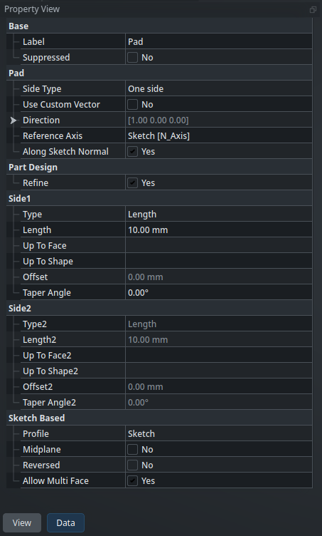
Another way to edit a feature is by selecting it in the Tree View and looking at its properties in the Property View. For instance, here are the properties of the Pad feature :
However, be careful : significantly modifying the geometry of early features in the timeline can easily break subsequent features, and therefore your model. This is a concept called model stability, and it’s not specific to FreeCAD : it is an underlying idea in every mechanical CAD software. Even though FreeCAD keeps getting better at recomputing models after they have been modified, it is still a good idea to follow some best practices. Broadly speaking, keep in mind that the less each operation depends on geometric features of the previous ones, the more robust your model will be.
Read more about the Topological Naming Problem on the wiki
The tip
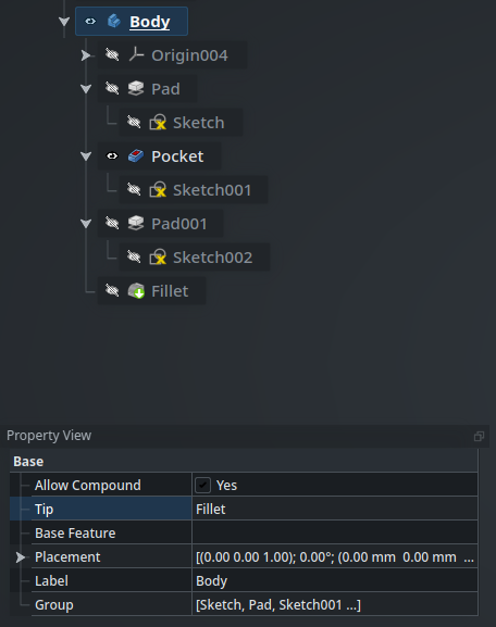
The final shape of the Body object itself (which can be referenced by other objects) is usually the shape of its last feature. However, this can be temporarily modified : Body objects have a property called their tip which points to the feature that is considered to be the final one, and which will be used as the shape of the Body. Here, this is the Fillet, and it is made evident by the green downward arrow on the icon of the Fillet, as well as the Tip property of the object :
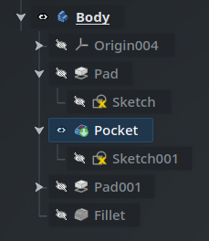
In order to move the tip of the Body, right-click on a feature and select Set Tip from its contextual menu. Here, I put the tip on the Pocket feature, and we can see that the green arrow has moved :
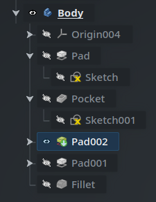
The tip is also the feature that will be used as the base feature when adding a new feature. For instance, if we add a new pad operation now, it gets inserted immediately after Pocket, and internally Pad001 is updated to depend on the newly-added Pad002 instead of Pocket (so as to keep a linear “timeline”) :
We can now move the tip and the visibility back on the Fillet (with right-click > Set Tip). This demonstrates how we can manipulate the “features timeline” — like you would do in “rollback state” in SolidWorks for instance. The crucial difference to understand is that what is usually a single cursor in other CAD packages, is two independent properties in FreeCAD : the currently-displayed feature used for visualization only, and the tip used for computations.
Base feature
One last thing about Bodies before we take a break. Since every feature is based on the previous one in the “timeline”, you might wonder : what is the first feature of a Body based on?
By default, the answer is simple : it is based on nothing. However, a Body can optionally have a base feature, which is a reference to another object (one which has a geometric shape) whose shape serves as the basis for the first feature of the Body.
A common situation where you will encounter this is when you need to modify an external STEP model. First, import it, either by using File > Import…, by hitting Ctrl-Shift-I, or by drag-and-dropping the file into the FreeCAD window :
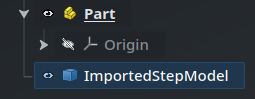
Note that this is a simple geometric shape, represented by a cube icon, not a Part Design Body object which has a staircase icon. It is not a container and cannot be modified directly.
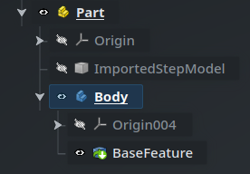
Now, while this model is selected, create a new Body. This Body will automatically have a BaseFeature child that references the imported object, with the tip set on it. The BaseFeature also has a green rightward arrow (not to be confused with the downward “tip” icon) that indicates that it is linked to another object (ImportedStepModel here). Since this Body now gets its shape from the imported model through that link, the imported model is automatically hidden to prevent seeing a duplicate in the 3D view :
Since the BaseFeature is only a link pointing to it, the ImportedStepModel object, though hidden, is still required. Do not delete it or your BaseFeature (and therefore its parent Body) will break. Keep it there as a kind of “resource” in the Part container : grouping these sort of things together is what Part objects are made for.
From there, we can create new sketches and features as usual based on this geometry to modify it, then export it back if we’d like.
We saw a lot of new concepts today, but I hope it was still easy to follow along, especially if this is not your first rodeo with parametric CAD software. Mainly, I hope that it helped make things click into place, and that the relationships between parts, bodies, features and sketches in the Part Design workbench now feel obvious. My goal is not to demonstrate what every feature does in this workbench — head over to the wiki and try them for yourself — but if you are familiar with CAD, you probably know the vast majority of them already.
Next time, in the fifth installment in this series, we’ll take a closer look at the Sketcher workbench, as well as how we cross-reference geometric elements between objects. See you then !