
This is the seventh part if this series already, how time flies ! Today, we’ll learn about another one of the core objects of FreeCAD : the Link object. We’ll also take a quick look at how we can specify the material of a part and customize its appearance.
Links
Fundamentally, a Link object is simply a sort of “pointer” to another object. It’s a lightweight wrapper that copies the shape and properties of its target object. As a metaphor, if objects were files, a Link would be what is called a “shortcut” on Windows or a “symbolic link” on Unix.
Links are used to create one or more copies of some object in an efficient and parametric way. For instance, if you have modeled a screw as a Part and you need multiple screws like this one in your model, instead of duplicating the part, you can simply create as many Link objects as necessary that all point to your original design. This has two main advantages :
- if you update the model of the screw, the change will be automatically reflected on all the instances;
- since all the Link objects only reference the shape of the original part without (usually) duplicating it, it avoids having lots of identical objects in your document, which is a lot lighter from a memory usage and file size point of view.
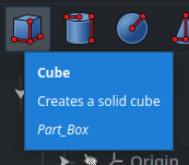
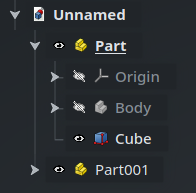
In order to experiment with Link objects, let’s create a simple Cube primitive inside Part (using the Part workbench) :
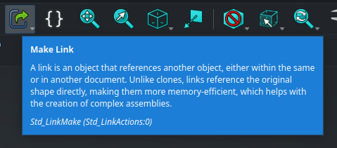
Now, let’s say that we want to create a linked copy of that cube inside Part001. Creating a Link object is very easy : simply select the target object (the Cube), then use the Make Link command from the core tools toolbar (next to the Datum objects) :
Another way to create a Link is to drag-and-drop an object in the Tree View while holding the Alt key.
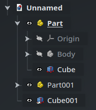
The Link will be created at the root of the current document. Here, FreeCAD has named it Cube001. Notice the small white arrow in the corner of the icon that indicates that it is a Link :
In order to put Cube001 inside Part001, we only need to drag-and-drop it in the Tree View :
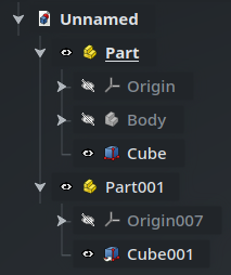
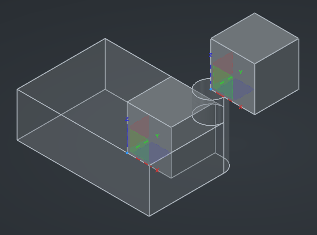
After doing this, you will notice that the cube has moved in the 3D view. This is perfectly normal : now the origin of the Link is relative to the origin of Part001, which, if you remember last episode, is attached to the top face of the cylinder :
Properties
If we select Cube001 and we take a look at the Property View, we can notice a few other specificities of Link objects :
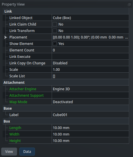
Link objects contain both a group of properties specific to the linking behavior itself (including the reference to the target object), as well as a copy of the properties of the target object (here, the dimensions of the cube under the Box category for instance — but also its attachment properties).
Some of these properties appear in green : this means that they are linked to the original object. Conversely, the other properties, in white, are specific to this linked instance. For instance, the Label property is specific to this instance (which makes sense considering labels must be unique), while the dimensions are shared with the original cube.
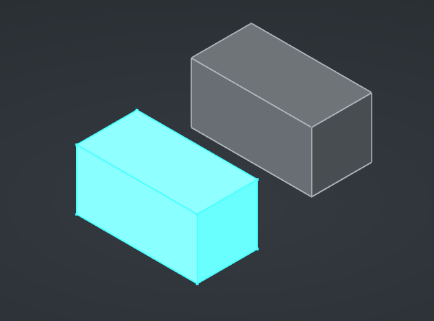
Let’s experiment with this. Select the original Cube and change its Length property to 20mm. You will see that both cubes change shapes simultaneously :
If you go back to the property panel of the Link’ed cube, you will see that its Length in green has been updated to 20mm as well. Furthermore, this link is bidirectional : change the Length property of the Link’ed cube back to 10mm and the original cube will update as well. Awesome !
Copy on change
This is very handy, very parametric. Sometimes, though, this is not what we want — instead, we do want to customize a specific instance of a Link’ed object. For example, we might have some screws with a Length property in our model, and we want some of them to have a different length than the others.
This is possible thanks to the Copy on change property of the Link object. The name “Copy on change” refers to the shape that the Link object takes, and you can understand it as “use the same shape as the target object by default, but if some linked property is changed, create a customized copy of the shape instead”. In order for a (linked — i.e. shown in green) property to trigger this behavior, it must be tagged with the special status CopyOnChange.
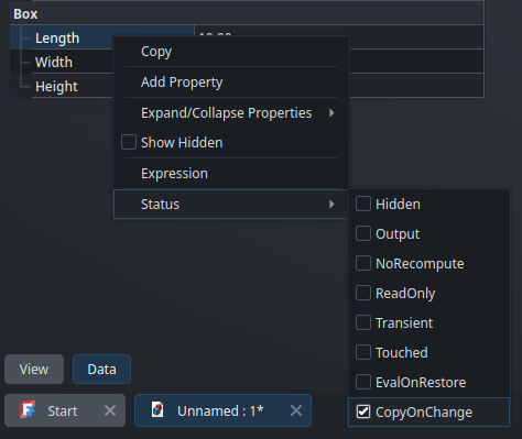
This will be easier to wrap our heads around with an example. First, select the original Cube and go to its properties. Then, right-click on the Length property, and check the CopyOnChange option under Status :
This means that this property can now be customized by any Link object pointing to this Cube, and that when the value of that property is changed on a Link object, instead of echoing this change to the original object, FreeCAD will internally create a copy of the shape inside the Link that it can recalculate independently of the original shape. This is exactly what we want in order to see screws of different lengths in our model.
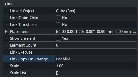
Next, we need to configure the Link object to allow it to create a copy (which it doesn’t do by default, in order to ensure that linked copies are as lightweight as possible in most cases). Select Cube001 and set its Link Copy On Change property to Enabled :
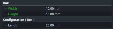
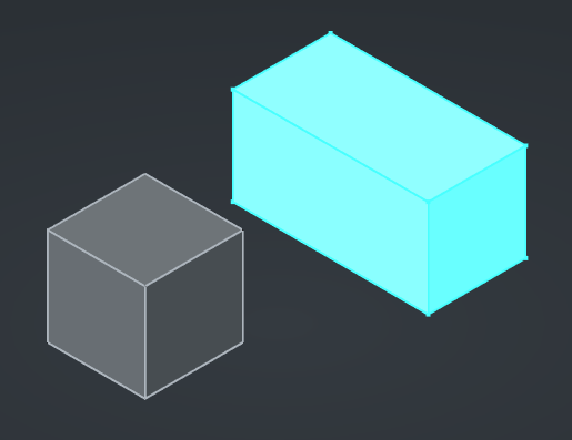
Now, set its Length property (of the Link’ed cube) to 20mm. You will see three effects simultaneously : first, the Length property becomes white and moves to a different group with the prefix “Configuration”; second, only the shape of the Link object gets updated in the 3D view; and third, the Link Copy On Change property switches to the Owned state (which means that the Link now “owns” a dedicated shape, independent of the original object) :
That’s exactly what we need. Perfect !
If you change the Width property of the original cube for instance, since it has not been marked with the CopyOnChange status, you might expect that this property would stay linked and that both cubes would get their widths updated. It looks like this is (at least as of this writing) not the case. I am not sure whether this is the expected behavior, or a bug in the current version of FreeCAD.
Cross-document links
Link objects can reference objects from other documents. This is a powerful feature that allows you to divide your project into multiple smaller documents.
Whether you prefer having one single large document for your project with everything inside, or one dedicated document for each part (as you may be used to if you come from SolidWorks for instance), or anything in between, is up to you — each way of doing things has its pros and cons, and FreeCAD gives you the flexibility to decide.
The process to create a cross-document Link is similar to the one we saw for the Sub-Shape Binder. Let’s create a new document imaginatively called Unnamed1, and insert a Cylinder primitive in it. In order to create a Link to this cylinder into our main document (Unnamed), we simply need to :
- make sure that both documents are saved to disk (so FreeCAD has a filename to use as a reference)
- open
Unnamed1and select the cylinder object - go back to the first document by clicking on its tab at the bottom of the screen
- click on the Make Link button in the toolbar
The Link will be created in the current document (the one whose name is in bold in the Tree View) and will reference the object selected in the other document. Since labels only have to be unique inside the scope of a document, FreeCAD was able to call this Link object “Cylinder” (no “001” suffix) without conflict. The icon in the Tree View displays two white arrows, to show that this is an external reference pointing to another document.
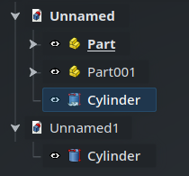
Cylinder object in Unnamed is linked to the Cylinder object in Unnamed1.If you open the Property View of the Link object, you will see that its Linked Object property says “
Unnamed1#Cylinder” : the hash separator indicates that the name to its left refers to the name of another document.
If you close FreeCAD and open Unnamed.FCStd again, FreeCAD will automatically find and open Unnamed1.FCStd as well in order to make the referenced object accessible, because its geometry is not saved inside the parent document.
Link objects also have two more advanced properties that you might be interested in for some use-cases : first, a single Link object is able to create multiples instances of the target object, using the Element Count property; and second, each Link instance can be scaled with a specific factor, using the Scale property. Experiment with them if they sound useful to you.
Links are a very handy feature to make your project more modular, and which give you options to organize it the best way possible. They are also widely used as the basic building block of Assemblies (in fact, I believe that’s even why the Link object type was added in the first place), as we’ll see in a future post. Don’t hesitate to use Links as much as possible where that makes sense for your projects !
Read more about Link objects on the wiki
Materials and appearances
FreeCAD offers two related but different properties that can be applied on objects : the material and the appearance. Let’s quickly look at them and how they are used.
The materials and appearances system is still under heavy development in FreeCAD, and the current features are still somewhat limited. Progress on this front is driven, among other things, under the umbrella of the FEP-0006.
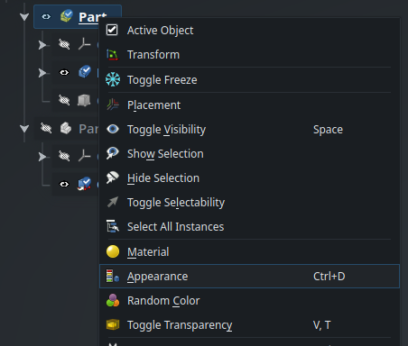
The appearance of an object is only a cosmetic property — mainly its color and transparency. It controls how the object is rendered in the 3D view and, depending on the format, may be included when you export a part. This property is available in the Property View under the View tab, but the best way to customize it is by selecting Appearance from the contextual menu of the object in the Tree View :
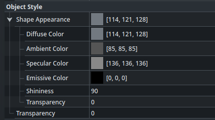
This opens the Display Property panel in the Tasks panel, where we can choose among some default appearances, or configure a custom one. For more information about the appearance properties (such as what diffuse, ambient or specular mean), take a look at this post : Explainer: Appearance Properties in FreeCAD.
There is also limited support to customize the appearance of some specific faces of an object. For this, select an object, then in the main menu go to View > Appearance per Face. This will open the eponymous option on the Tasks panel. From there, you can select some faces and an appearance to apply on them. That feature does still suffer from the toponaming problem though, so if you modify your model, the custom appearance may move to another face. It is recommended to only do this when you are done modeling your part, as cosmetic cherry-on-top.
Materials are a broader concept than simple appearances : a material contains both appearance information and physical material information. When a material is specified for an object, some functions and workbenches, such as the CAM workbench and the FEM workbench, may use this information for specific purposes (such as calculating the mass of the object or making simulations on it). Specifying a material on an object also updates its appearance accordingly, although this appearance can be modified again afterwards.
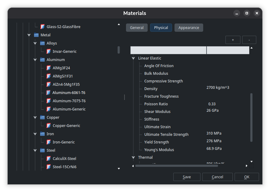
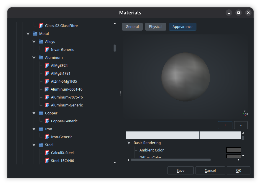
In order to specify a material on an object, use the Material option from its contextual menu, just above the Appearance option (see the screenshot of the contextual menu above). FreeCAD ships with a database of default materials, including as a range of metals, each having their exact physical properties already configured. In order to explore existing materials and create new ones, click on Launch Editor in the Tasks panel. For instance, here are the physical properties and appearance of the Aluminum-6061-T6 material in the editor :
That’s it for today’s subjects, so let’s take a break ! Next time, we’ll look at how to create mechanical assemblies by combining multiple parts and specifying constraints and degrees of freedom between them.