
As we’ve seen earlier, thanks to attachments especially, we are easily able to create in FreeCAD complex models containing lots of parts fixed to each other, and this workflow suits perfectly a lot of projects.
For some others, though, it may not be very practical. If, instead of designing everything from the bottom up, we want to create something mainly based on external parts that we downloaded from a manufacturer’s catalog or imported from another CAD software, attachments may be a bit cumbersome to use. Furthermore, attachments are static — they have no degree of freedom — so if we want to model a mechanical system with moving parts, they are not the tool for the job.
For these use-cases (among others), what we need is an assembly.
If you have experience with other CAD packages, you are probably familiar with this concept. Using assemblies, you can “include” some mechanical parts in a system, specify constraints or degrees of freedom between them, simulate movement, and watch how everything interacts — almost like having a mock-up on your bench.
So let’s look at how we can make an assembly in FreeCAD !
Assemblies
In FreeCAD, an Assembly is a container object that is positioned in space (it has an origin), that can have the active status, and which automatically has a Joints group as a child. It is somewhat like a super-Part that is able to manage how its children should move relative to each others.
To illustrate how assemblies work, we will use an example model from the wiki : a universal joint. Credits for the idea and this model belong to the original author, which I believe is Edi271.
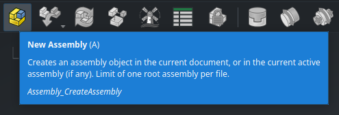
Setting up a simple assembly in FreeCAD is pretty easy. We’ll start with a new document. First, go to the Assembly workbench, and create a new Assembly object :
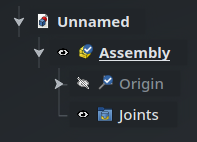
In order to interact with an assembly, it must be active — which is the case by default when we create it. We can also see the Joints group, which is empty at the beginning.
We now need some parts to assemble : we’ll use the Fork and the Cross parts from the wiki. You have three options here :
- model them yourself with the Part Design workbench based on the screenshots below if you want to practice;
- use the Python code below to create them directly;
- or simply download the project file.
In order to import this Python code, go the main menu at the top of the screen and select View > Panels > Python Console. This will open the Python prompt at the bottom of the screen, where you will then be able to copy/paste directly the code below. Press Return to make sure the last line of code is executed. You can then close the panel.
import math
import FreeCAD as App
import FreeCADGui as Gui
import Part

doc = App.ActiveDocument

sph1 = Part.makeSphere(50, App.Vector(0, 0, 0), App.Vector(-1, 0, 0), 0, 90, 360)
box1 = Part.makeBox(50, 40, 80, App.Vector(-50, -20, -40))
cyl1 = Part.makeCylinder(20, 80, App.Vector(0, 0, -40))
cyl2 = Part.makeCylinder(20, 80, App.Vector(0, 0, 0), App.Vector(-1, 0, 0))
cyl3 = Part.makeCylinder(30, 60, App.Vector(0, -30, 0), App.Vector(0, 1, 0))
box2 = Part.makeBox(30, 60, 60, App.Vector(0, -30, -30))
cyl4 = Part.makeCylinder(15, 80, App.Vector(0, 0, -40))
cyl5 = Part.makeCylinder(15, 80, App.Vector(0, 0, 0), App.Vector(-1, 0, 0))
shape = sph1.common(box1).fuse([cyl1, cyl2]).cut(cyl3.fuse([box2, cyl4, cyl5]))
fork = doc.addObject("Part::Feature", "Fork")
fork.Shape = shape.removeSplitter()
fork.Placement.Base = App.Vector(0, 0, 0)

cyl1 = Part.makeCylinder(15, 80, App.Vector(0, 0, -40))
cyl2 = Part.makeCylinder(15, 80, App.Vector(0, -40, 0), App.Vector(0, 1, 0))
shape = cyl1.fuse([cyl2])
cross = doc.addObject("Part::Feature", "Cross")
cross.Shape = shape.removeSplitter()
cross.Placement.Base = App.Vector(70, 0, 0)

mat = fork.ViewObject.ShapeAppearance[0]
mat.DiffuseColor = (0.80, 0.60, 0.15, 0.0)
fork.ViewObject.ShapeAppearance = (mat,)

mat = cross.ViewObject.ShapeAppearance[0]
mat.DiffuseColor = (0.55, 0.70, 0.70, 0.0)
cross.ViewObject.ShapeAppearance = (mat,)

doc.recompute()
view = Gui.ActiveDocument.ActiveView
view.viewIsometric()
view.fitAll()
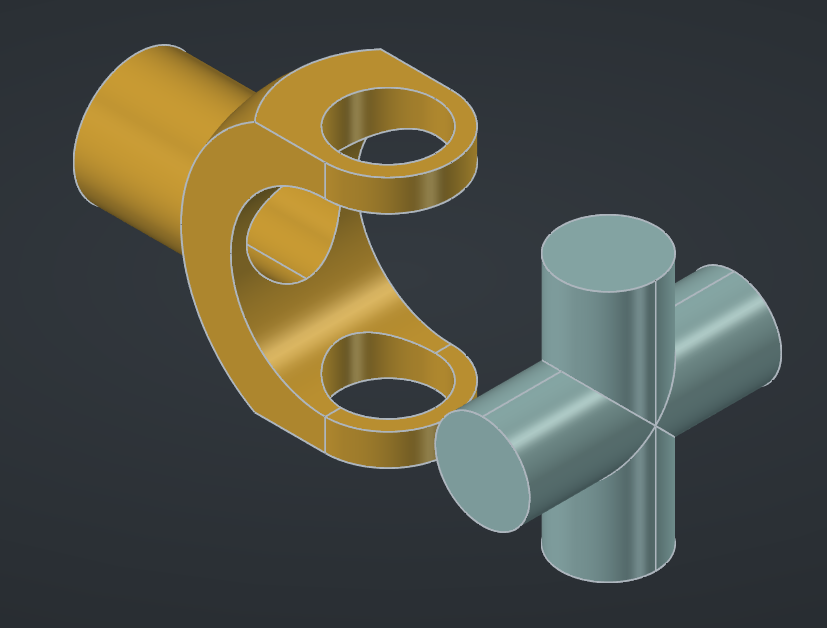
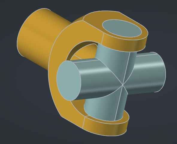
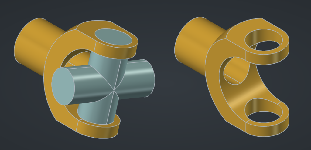
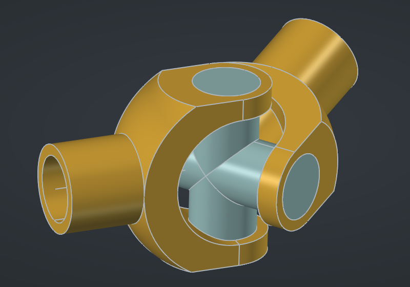
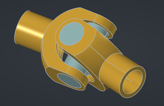
Here is what the two parts look like :
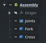
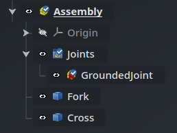
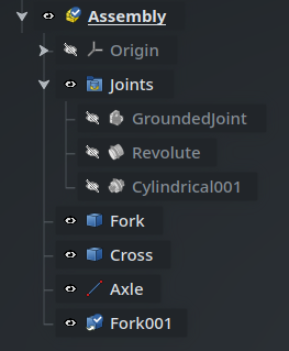
Now, we need to include these parts into the assembly, and for this, we have two options : either insert them as Links using the Insert Component command, or put the parts directly as children of the assembly. If we wanted to assemble a set of parts each defined in a separate file, the advantage of the Insert Component is that it is able to directly open an external file and reference a part inside it. In this example we don’t need it though : we can simply select both parts in the Tree View (Fork and Cross) and drag-and-drop them onto the Assembly object (remember that you can use T D to initiate dragging). At this point, the document should look like this (make sure that the assembly is active) :
I’m using the word “parts” here, in lowercase, in the general sense of the term — these objects or not of the Part type.
Grounding
The first thing to do in an Assembly is to ground a part — i.e. make it fixed relative to the origin of the assembly. Otherwise, the whole system would be able to move anywhere in 3D space, like a piece of string in zero gravity, and it would pretty difficult to manipulate the assembly.
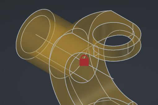
Select the Fork part, and click on the Toggle Grounded command in the toolbar (or use the shortcut G) :
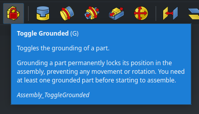
A red padlock will appear on the object in the 3D view, and this constraint will be shown inside the Joints group in the Tree View :
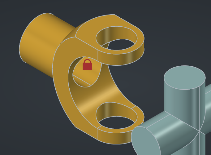
You can see the effect in action : try dragging the cross on the screen, you will see that you are able to move it anywhere you want; but if you try the same with the fork, it will stay in place.
In case the cross doesn’t move either, make sure the Assembly is active : you can only move parts inside an active assembly.
However, that’s not exactly what we want. For our system to work, we need the fork to be able to rotate. We need something else as the grounded part — something that would represent the axle around which the fork rotates.
Construction guides
We could model a specific part for this, but instead we will use a simple line as a kind of construction guide to help us define the joints that we need — a bit like how a construction line in a sketch helps setting up constraints.
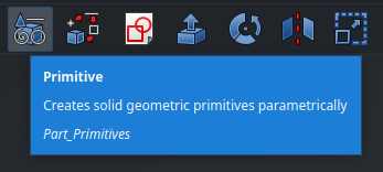
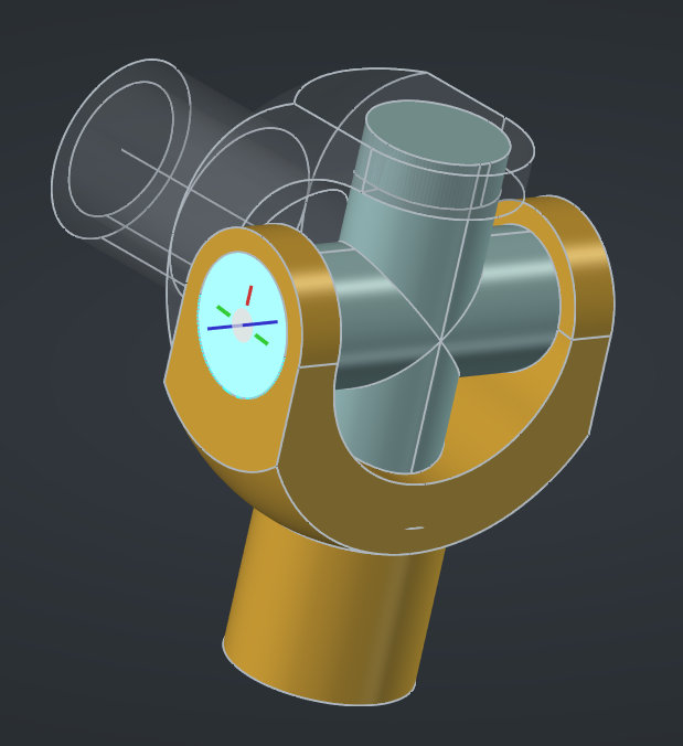
Go to the Part workbench and select the Primitive command in the toolbar :
In the Task panel, select Line and set the end to X=-80mm (that’s the length of the fork), with all the other dimensions to 0mm :
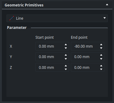
Hit Create then close the panel. The line is added at the center of the fork, and you can rename it to “Axle” :
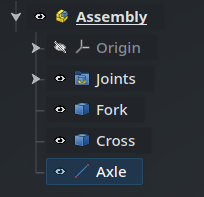
Now, we can go to the Joints group in the Tree View and delete GroundedJoint, then select the Axle and set this part as grounded instead, using the same command as before (or G). We can also hide the new GroundedJoint001 to remove the padlock from the 3D view.
Joints
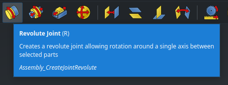
Joints are objects defined inside an Assembly that control the degrees of freedom that two parts of the assembly have relative to each other. Here are the available joint types :

The icons are pretty self-explanatory : for instance, the first is a Fixed joint which doesn’t allow any degree of freedom, the second is a Revolute joint which allows a part to rotate around a specific axis relative to another, and so one. Take a look at the wiki to learn more about all the available joints.
When defining joints inside an assembly, start with the grounded part, then apply joints in series in an order that ensures that, for each joint, at least one of the two connecting parts is connected directly or indirectly to the grounded part. In other words, try to avoid joining two floating parts together. This will help the solver place the parts in a consistent way.
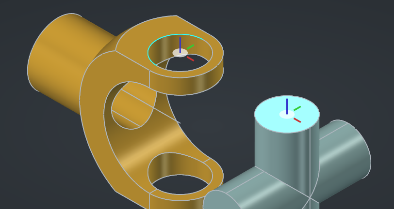
In this case, we need to start by making the fork rotate around the axle. For this, we need a Revolute joint :
Select the joint from the toolbar or hit R. Now, when hovering over features in the 3D view, you will see a small gizmo centered on that feature, like this :
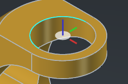
In order for the joint to work, we need to select two geometric features like this (which belong to two different parts, obviously). Note the colors of the axes : for most joints, the Z axis, in blue, will be used as the main axis of the joint.
Let’s hide the cross for now, and move the fork out of the way. Select the circle at the base of the fork, as well as the end of the axle line :
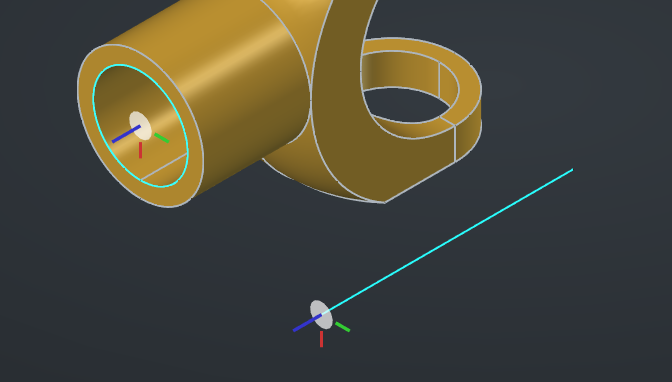
Notice that the two blue axes are correctly aligned : the joint will make them coincident. For the axle, if the blue axis points up, try moving the cursor further down the line : what you actually need to select is not the vertex at the end of the line, but the line itself close to its end (it should turn blue). When hovering over the line, you will see that you can snap the gizmo to either end as well as to the center. There is no better way to understand this than to move the cursor around and practice for yourself.
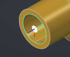
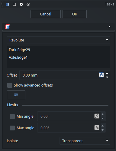
When the two references are selected, FreeCAD will align the parts automatically :
In the Tasks panel, you will find a few options. For instance, you can add a linear offset : this will move the references of the parts away from each other along the joint’s Z (blue) axis (type a negative value to reverse the offset). We don’t need it here because we specified the exact length needed for the line of the axle. You can also specify angular limits to the joint, which we also don’t need here because the fork can rotate indefinitely around its axle.
Click Ok — the joint will appear in the Tree View. Now, try to move the fork in the 3D view by dragging it : you will see that it rotates around the axle, but it doesn’t move in any other way. Great !
Now, let’s make the cross visible again and connect it to the fork. This time, we will use a Cylindrical joint (C) :
Why not a Revolute joint, you may wonder? Well, it would work, but it would be more constrained that it needs to be. Once all the joints are defined, the inner cross part won’t be able to translate inside the forks thanks to how the universal joint works. It’s always a good idea to use the most permissive joints possible in an assembly, because it prevents it from approaching an over-constrained state, and it helps the solver find a solution in every position. If you have issues with an assembly “exploding” while trying to drag some parts, try to relax some constraints on the joints (by changing a Revolute or a Slider into a Cylindrical for example).
Our universal joint is starting to take shape, but we need another fork. Since it is the same as the first one, we can create a simple Link : select the Fork object, then click on the Make Link button in the toolbar. The Link object will be created at the root of the document, so we need to drag it inside the Assembly, and we can then move the copy away to the side :
Then add a second Cylindrical joint (C) between the cross and the second fork :
Finally, we need to constrain the second fork to another axle which will act as the “output shaft”. Add a new line from the Part workbench with its endpoint at X=80mm (and all the other coordinates to 0mm), rename it Axle2, and add it to the assembly. We need to constrain it to the first axle : for this, we can use a Fixed joint (F). In order to make things a bit more interesting, we can specify a rotation offset of 20° in the properties of this joint — after all, the whole point of a universal joint like this is to transmit a rotation between two axles that are not aligned. Finally, add yet another Cylindrical joint between the end if this line and the second fork :
Try to drag the first fork around and observe how the assembly moves dynamically and how the joint operates. Awesome !
For more complex systems, FreeCAD supports setting up nested sub-assemblies.
Read more about assemblies from the wiki
Animation
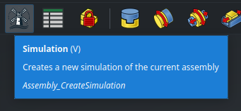
To illustrate our mechanical system even better, we can animate it using a Simulation. Start by creating a new simulation using the toolbar :
In the Motions window in the Tasks panel, add a new motion on the last joint (the one between the second fork and the second axle), with the motion type Angular, and the following formula :
2 * pi * time
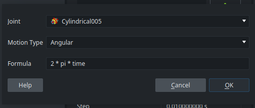
time is a special variable that tracks the current time step — since the angle of the joint now depends on time, it will be animated. Keep the settings to their default values and hit Generate. An animation player will be displayed :
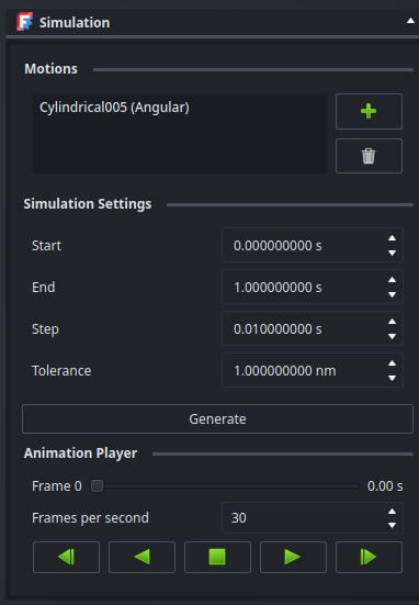
Let’s hit play and watch FreeCAD bring our mechanism to life ! If you need, you can now click Ok to save this simulation in the Tree View, you will be able to open it again later.
If you want to practice, try adding another motion to slowly animate the angle between the two axles and illustrate even better how the mechanism adapts while rotating. You may want to use the
sin()function to have the angle oscillate between plus or minus 25°. Be aware of your units when working with angles (radians or degrees).
Read more about simulations on the wiki
That’s it for this overview of assemblies in FreeCAD ! Next time, for the last post in this series, we will talk about a more advanced but very interesting feature : configurable parts.