
FreeCAD has the reputation to have a steep learning curve, but I don’t thing that reputation is still deserved nowadays. There are some basic ideas to grasp in order to get started, but to be fair that can be said of any software as complicated as a parametric CAD modeler — and if you come from Fusion, Onshape, SolidWorks or similar software and you are already familiar with the common concepts of this kind of tools (such as sketches, extrusions, or construction geometry), you should feel quickly at home with FreeCAD.
My goal here is not to teach you CAD modeling (though I will start from the basics as much as possible, so you shouldn’t feel lost even if you are not a CAD expert), nor to offer a complete and thorough presentation of everything that FreeCAD has to offer — for this, you may want to take a look at the official wiki, or to get yourself a copy of FreeCAD Beginner’s Handbook by Aleksander Sadowski. Instead, I will try to summarize the most important concepts specific to FreeCAD as efficiently as possible, one topic at a time, in order to get you started quickly and smoothly.
Today, we will learn about Documents, Objects, Properties, and Workbenches. Without further ado, let’s dive in !
Documents
Let’s start with the basics. A FreeCAD file is called a document. A document is a generic container that can contain any number of objects (see below), distributed into a hierarchy — somewhat like a folder with different files inside. When designing a project in FreeCAD, you can put everything you need in a single document, or split it into multiple smaller ones if you’d like.
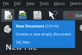
Create a new document (which will be called “Unnamed” by default) using the first icon in the toolbar :
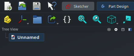
Multiple documents can be open at the same time in a single FreeCAD window. Open documents are displayed in the Tree View on the left :
… as well as in the tab bar at the bottom of the screen, next to the Start page :

A document can reference other documents in order to link objects together (more on that later). When this is the case, when you open a “parent” document, FreeCAD will automatically open the “child” documents as required. The “child'” documents will be displayed in the Tree View panel on the left in order for you to access them, but not in the tab bar on the bottom by default so as not to make it feel overcrowded. Open them as needed by double-clicking on them in the Tree View, and they will show as dedicated tabs.
Read more about documents on the wiki
Objects
An object is the most basic building block in FreeCAD. Each object has a type, and there are lots of different types of objects that you can combine to design your project. Sketches, features, geometric bodies, parts, meshes, surfaces, construction planes, coordinate systems, spreadsheets, variables sets, measurements, FEM analysis specifications, … each of them is an object. Don’t feel overwhelmed by the number of types of objects though : you only need to learn them as you need them.
Objects are mainly created from the buttons in the main toolbar, or equivalently, from the menu at the top of the screen. Objects contained in the current document are listed in the Tree View on the left. Some objects can act as containers and contain other objects, which is why objects are displayed as a tree. This is only a visual way to represent a dependency though, sometimes the same object can be contained by multiple parents (such as a sketch shared by two different parts), in which case the same object will appear multiple times in the tree.
Only a handful of objects are provided by the core of FreeCAD — most are provided through modules (called workbenches), which we will see later. The core objects are simply these ones :
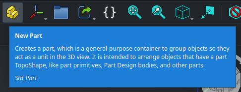
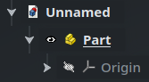
The first one (the yellow staircase) is a Part, which is a generic container object that can be used to group together related objects (such as 3D bodies or construction geometry) that define a unique mechanical part in a system. It usually contains 3D objects so it comes by default with an Origin to attach its position and orientation in space. When an object (such as a 3D body) is a child inside a Part object, its position is specified relative to the origin of its parent Part, so moving the Part will move all the child it contains ; and if the parent Part is hidden, its children are hidden as well. So far so obvious. Furthermore, a Part can also contain other Parts to group “sub-systems” together and organize more complex projects easily.
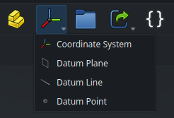
The second icon is a drop-down menu that can be used to create datum objects (coordinate system, plane, line, point), equivalent to what is sometimes called “construction geometry” in other CAD software.
The last 3 icons are groups, links and variable sets — we will cover those as needed, but by the end if this series, they will no longer have any secret for us. For now, start by creating a Part, by clicking on the yellow staircase. It will appear in the Tree View on the left.
Objects visibility
Some objects have a visual representation in the 3D view at the center of the screen, such as 3D bodies or sketches. Some don’t and only contain data, such as variable sets. For those that do, there is a small eye icon next to their name in the Tree View to control their visibility in the 3D view. The visibility of the currently selected object can also be toggled using the space bar as a handy shortcut, which is something you will use a lot.
Selected and active objects
An object can be selected, by clicking on it either in the 3D view or in the Tree View. This is represented by a highlight around the object’s name. Any number of objects or 3D geometry elements of any types (faces, edges, …) can be selected at the same time, by pressing the Ctrl key while clicking on the relevant items.
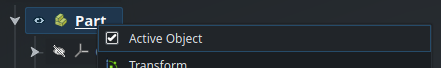
A few types of objects (mainly Parts and PartDesign Bodies, which we will see in the next post in this series — but also Assemblies, which we’ll cover a bit later) can also be active, which is represented with a bold and/or underlined name in the Tree View. An object is activated or deactivated through the Tree View, either by double-clicking on its name or right-clicking and checking/unchecking the “Active Object” box at the top of the contextual menu.
Only one object of each type can be active at a given time, so for instance activating a Part will deactivate the previously active Part. Also, if you activate a Body contained inside a Part, it will automatically activate its closest parent Part.

In the Tree View, the current document is also considered active when its name is in bold. This corresponds to the selected document tab at the bottom of the screen, and the model that is currently displayed in the 3D view. Another document can be made active be switching to its tab, or double-clicking on its name in the Tree View.
Most functions and commands all around FreeCAD interact with the selected and/or active object(s) as their target, so it’s very important to be aware of which objects are currently selected and active before trying to execute something. For instance, some commands use the selected object as some kind of reference to modify the active object. In order to make things more intuitive, some buttons in the menu will dynamically be enabled or disabled depending on what is currently active and selected.
Here is a quick tip : when clicking in the 3D view to select items, each new click on the same element will select the parent of the whole item currently selected. For instance, let’s say you have a Cube object inside a Part, and you click on a face of the cube in the 3D view. The first click will select the face, the second click will select the entire Cube, the third click will select the parent Part object (with all other objects that this Part contains next to the Cube), and so on. Since there is no parent above the Part, the fourth click will circle back and revert the selection to the single initial face.
Groups
To organize things better, some objects can be grouped together in the Tree View by creating a Group. This is the third core object that we saw earlier :
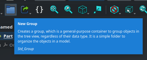
Once a Group is created, you can drag-and-drop objects inside it in the Tree View.
Dependencies
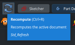
Some objects can depend on each other. For instance, a geometric shape may depend on an extrusion feature, which itself may depend on a sketch, which itself may contain dimensions that depend on a variable set. Internally, FreeCAD models the relationships between all objects in your document as a graph. When the variable set is modified, FreeCAD knows that all the other objects that depend directly or indirectly on it needs to be recomputed. In most cases, it will perform the recomputation automatically and everything will be updated instantly — this is the beauty of parametric CAD modeling. Sometimes, though, this recomputation may be deferred for performance reasons, and instead the object will show a small blue tick to mark it as “needs to be recomputed” :

In that case, hit Ctrl-R or click on the Recompute button in the toolbar, the blue mark will disappear and the model will be updated.
When designing your project and creating references between your objects, you need to make sure that it won’t cause circular dependencies between them, otherwise FreeCAD won’t be able to know in which order it needs to recompute them. Fortunately, in case this happens, FreeCAD will warn you and you will be able to organize things differently.
Internal name and label
I’ve been talking about the “name” of objects above, but objects actually have two different “names” that serve different purposes.
The label of an object is the user-facing name that is displayed in the Tree View. It helps you know what the object represents in your project. You can (and should !) rename objects (i.e. change their labels) in your document in order to keep things readable and organized, especially if you plan on sharing your project. This is done either through the contextual menu of the object in the Tree View (right-click > Rename) or by pressing F2 when an object is selected. Each label must be unique in your document, and FreeCAD will enforce this by appending a suffix like 001 if it detects a conflict.
Objects also have an internal name. This internal name is assigned automatically when the object is created and cannot be modified. It is used internally in the dependencies between objects in order to reference them uniquely in a way that won’t break when objects are renamed. This is rarely necessary, but in case you need to find the internal name of an object, you can either have them shown in the Tree View by right clicking on it and checking Tree Settings > Show Internal Names, or by hovering over the object and looking at the status bar at the bottom of the screen (if it is not displayed, make sure View > Status bar is enabled in the menu at the top of the screen). Here, the label is “My Part” and the internal name is “Part” (the next one would be called Part001, and so on).


Read more about names and labels on the wiki
Properties
Objects have properties, in the form of a list list of key/value pairs, that define the specifications and behavior of the object. The properties that are available for a given object depend on its type. Depending on the type of each property, its value can be either some text, a number, a dimension (a number with a unit attached), a color, a reference to another object, …
The properties of the currently selected object are displayed in the Property View panel, located by default under the Tree View, and are divided into two tabs called View and Data :
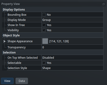
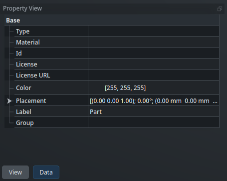
Here, for the Part object, we can see that we have for instance properties related to the position and orientation of the object in 3D space (called its placement, more on that in a future post), its label, its color, and that we can make it transparent if we want.
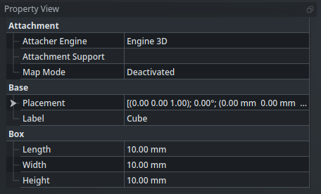
More interesting objects have more properties. For instance, a simple cube object has properties for its length, width and height under the Box category :
Some less-useful or internal properties are hidden by default to make things more readable, but can be displayed by right-clicking in the panel and checking Show hidden.
One of the most powerful features of FreeCAD (unmatched by any other CAD package that I know of) is that all properties of an object can be referenced by other objects, and conversely, all properties can be driven by expressions. We will learn more about expressions in a future post, but for example, having a Cylinder object whose diameter is automatically (parametrically) twice the width of a separate Cube object, is as simple as writing a small expression to link the properties of both objects — FreeCAD will then manage everything for you.
If you have multiple objects of the same type, you can select any number of them and edit any property — it will update that property for all the selected objects at the same type.
Custom properties
It is even possible to create custom properties on objects, that can be used to expose some parameters whose values are used in expressions inside the object. To add a custom property on an object, simply go to its Property View, then right-click anywhere and chose Add Property. For instance, let’s say you have modeled a staircase for your house. You could add a custom “StepHeight” property on that Part, that you could then use as a parametric variable in expressions for sketch dimensions or extrusions lengths :
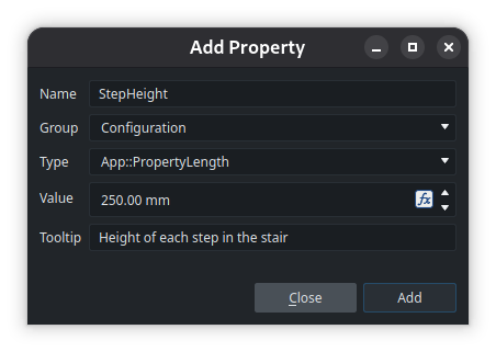
It will then be available in the Property View under a new “Configuration” group :
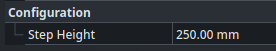
If you write your property name as camel-case (i.e. without spaces but with uppercase letters to separate the words), FreeCAD will automatically insert a space before each uppercase letter in the Property View to show a clean menu. In expressions, the parameters should still be referred to with its real name
StepHeightwithout spaces, though.
Workbenches
FreeCAD is deeply modular, and most features are organized around workbenches. A workbench is a module that provides a collection of tools and functions related to a certain task or domain, and allows creating and manipulating objects relevant for this domain. For instance, the Sketcher workbench is used (unsurprisingly) to create Sketch objects, and contains all the tools required for this task : creating lines, circles and other 2D geometric primitives; transforming and manipulating these primitives; adding constraints on them; and so on. If you are familiar with Fusion or SolidWorks, this is very similar to the “workspaces” of the former, or the tabs in the main ribbon panel of the latter.
By default, the current workbench is selected from a drop-down menu, but we changed it to a tab-bar, displayed in the main menu at the top of the screen :

Selecting a different workbench updates the UI to display the relevant toolbars, buttons and menus for this workbench.
FreeCAD comes bundled with a good number of workbenches by default (not all of them always useful, which is why we kept only the most important ones when we tweaked the configuration — though the other ones are still available through the drop-down menu under the green “+” icon). A lot of third-party workbenches are also available from the Addon Manager. Three quality addons that I recommend are the Fasteners workbench, the Sheet Metal workbench, and the Curves workbench.
Read more about external workbenches on the wiki
This concludes part 3 of this series. This was more on the “theoretical” side of things and I hope I didn’t lose you along the way, but keeping in mind the core concepts that we saw today should help prevent any confusion later and will ensure that working with FreeCAD feels obvious and logical. See you in the next episode to start drawing things !