A pragmatic introduction to FreeCAD – part 5 : sketches and references
In the last post, we learned how FreeCAD’s Part Design workbench works and how to design a part with it. However, in this demo we used sketches as bare as possible in order to move quickly. Today, we will take a closer look at the Sketcher workbench, and how external geometry references work.
Sketches
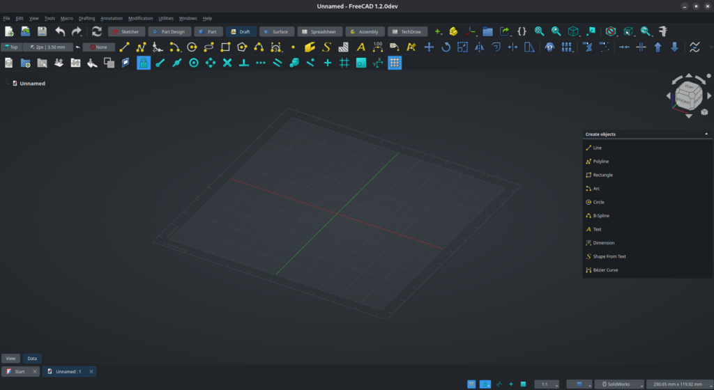
Let’s start from scratch with a new empty document. From there, make sure you are in the Part Design workbench, create a first Part, then a Body inside it.
Make sure the Body is active, then create a new sketch, either using the toolbar or (if the body is selected), from the Tasks panel :
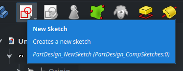
New Sketch from the Part Design toolbar.
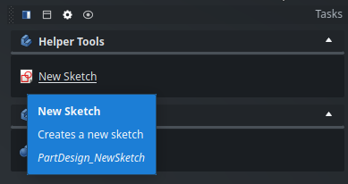
New Sketch from the Tasks panel, when a Body is selected.
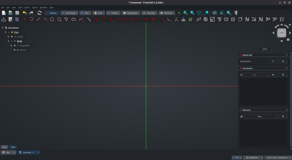
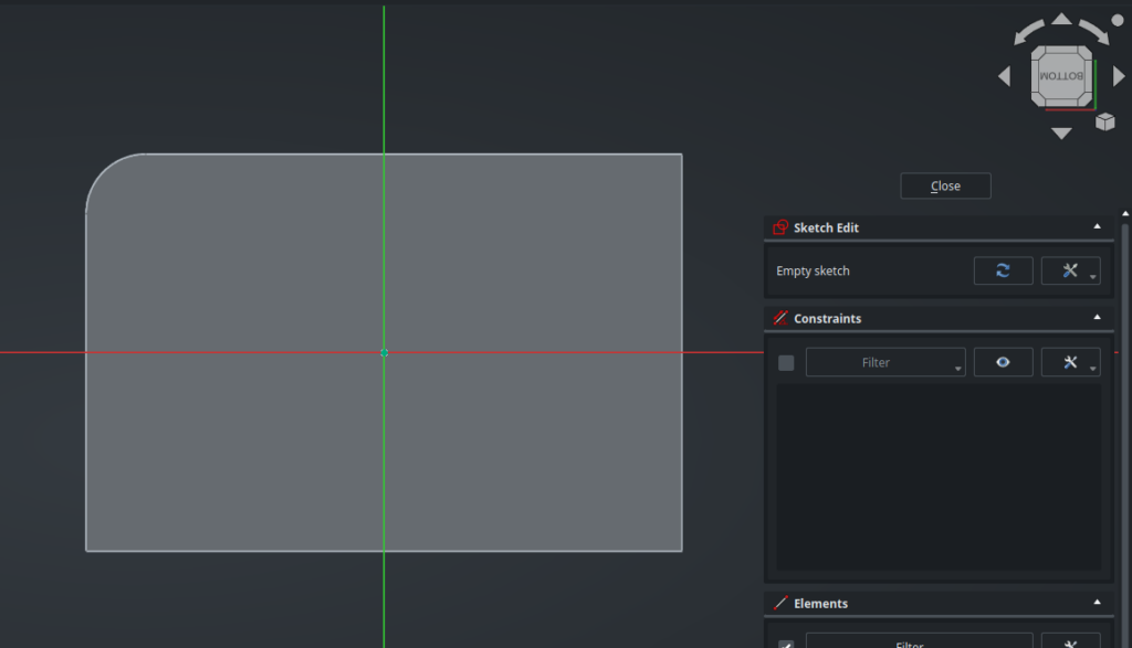
Select the XY plane. The 3D window will move to the Top view and you will be presented with an empty sketch, with an origin and X (red) and Y (green) axes.
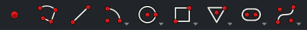
The toolbar is divided into 3 main sections :
2D geometry primitives
constraints
transformation functions
There are also more advanced functions toward the right, dedicated to working with B-splines. If you don’t know anything about B-splines, don’t be intimidated and ignore these buttons for the time being.
I won’t go into the details of every primitive and function : if you have a bit of experience working in mechanical CAD they probably won’t need much presentation; otherwise, read the tooltip of each button and take a look at the reference documentation on the wiki. My goal here is to give you enough information to get started, while distilling a few tips and tricks along the way.
Geometry primitives
The usual suspects are available here : lines, rectangles, circles, arcs, polygons, splines, and so on. Notice the drop-down menu on most of them : one tool can hide a few others if you click on the bottom right of the button. Click on any tool and start drawing in the 3D view.
The basic Line tool (third icon) creates single individual lines. However, like all other tools, it stays selected after you draw an element, so you can draw multiple lines in a few clicks. If you want to draw an arbitrary shape, use the Polyline tool (second icon) instead. When you are done, either right-click or press Esc on your keyboard to deselect the current tool.
Most of the 2D primitives tools in the Sketcher workbench have a handy keyboard shortcut to help you being more efficient, and I encourage you to use them. They are pretty easy to remember, and once you get used to them they speed things up significantly. In order to use the available keys more efficiently (because there are lots of functions and keybindings in FreeCAD), these shortcuts are actually a sequence of keys, and the 2D primitives tools start with the G key. For instance, in order to draw a Rectangle, press the G key, then the R key. There is also G L for a Line, G C for a Circle, G P 6 (think “polygon”) for an hexagon, an so on. The shortcut of each tool is listed in the tooltip of the corresponding button in the toolbar.
Some tools have different modes of operation, which you can toggle using the M key. For example, when drawing a Polyline (G M), type M to cycle through the modes : straight line, right-angle corner, arc, and so on.
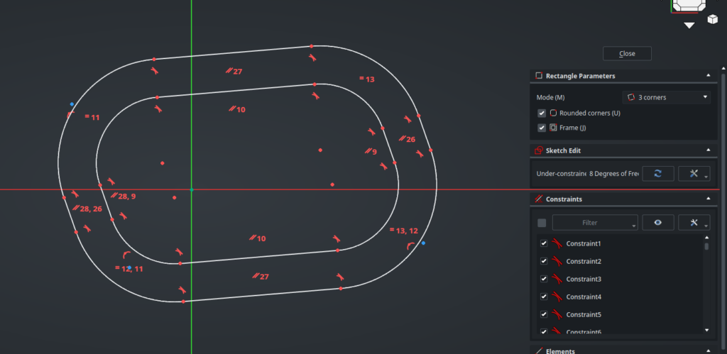
Some tools also have options available in the Tasks panel. The Rectangle tool, for instance, has different modes of operation, and allows you to directly create rounded rectangles and/or framed rectangles. Since at this point your mouse cursor is busy tracing the object in the 3D view, the easiest way to select these options is with the keybindings : hit M to change the mode, U to toggle rounded corners, or J to toggle the frame. As a complete demonstration, here is a rounded, framed rectangle based on 3 corner points, drawn with a single tool (I used G R to select the Rectangle tool, then hit M M, U and J, then made a few clicks on the 3D view) :
A complicated shape made easily using the advanced options of the Rectangle tool. Note the three blue points : they are the 3 corners that serves as the base of the rectangle.
When using a new tool, remember to take a look at the advanced options it offers, you would be surprised by how powerful some are.
In case you have moved the orientation of the 3D view, you can quickly come back to the normal view above the sketch plane either by right-clicking on the background of the 3D view and selecting Align View to Sketch, or by pressing Q P.
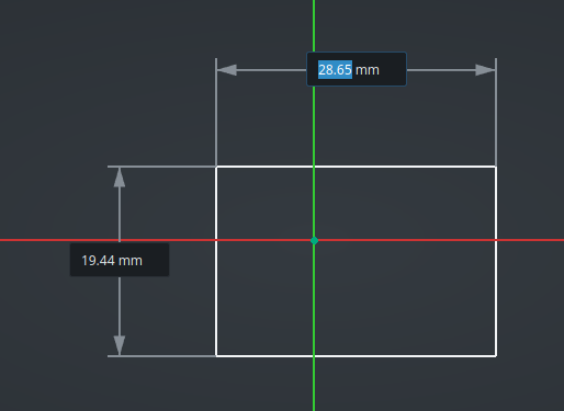
Most tools also offer you the opportunity to directly type the dimensions of the shape you are drawing, while you are drawing it. For example, with the Rectangle tool, after clicking a first time in the 3D view you will see :
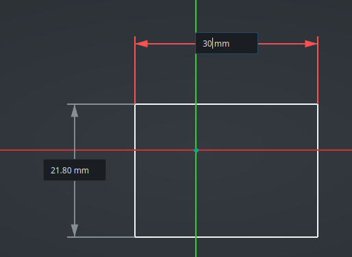
If you simply click a second time to validate the other corner of rectangle as-is, these dimensions will disappear. However, if you start typing a number, the arrows will turn red and the rectangle will obey the exact horizontal dimension you specify :
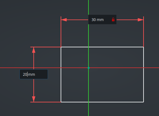
Hit the Tab key to switch to the vertical dimension and type another value :
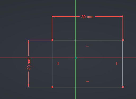
Then either left-click anywhere, or press Enter, to validate the new rectangle. The dimensions will stay in place :
Constraints
This is a good transition to talk about constraints, because dimensions are a kind of constraints. In the broad sense, constraints are rules that you apply on your geometry elements in order to mold them into the exact shape you want. The goal is to add just enough constraints to remove all degrees of freedom from your sketch, which means everything is placed purposefully and nothing is left to chance depending on where exactly you clicked on the screen when drawing the elements. For example, here, the rectangle now has an explicit size, which is a good thing; however its exact position is pretty random because we clicked “somewhere around the top and left of the origin” to place its top-left corner — this is not acceptable in a well-designed mechanical part.
Since we are missing constraints on the position of the rectangle, that means it can move. Click on a vertex or a line of the rectangle and drag it on the screen to see this degree of freedom in action.
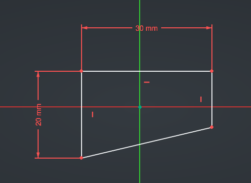
The current constraints applied on your sketch are shown in the 3D view, as well as in the Tasks panel. Some tools automatically apply constraints on the elements of your sketch when it is relevant. Here, the Rectangle tool has added Horizontal and Vertical constraints on the lines, in order to make sure they keep a rectangular shape : this is the small red icons that you can see next to the lines. You can click on one of these constraints (or select it in the Task panel) and remove it (by hitting the Del key), which will give you more degrees of freedom to change the overall shape of the elements :
The Horizontal constraint on the bottom line has been removed, and the bottom-right corner has been moved.
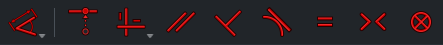
By using the available constraints, you can force elements to stay coincident, parallel, tangent, have equal length, and so on :
The available constraints in the toolbar. Some have multiple meanings depending on the kind of geometry that is selected (like the Tangent/Collinear constraint).
Some constraints require two (or more) elements to be selected in order to work (for instance, the Coincident constraint which, as its name implies, makes a thing coincident to another thing). In that case, press the Ctrl key while clicking in the 3D view in order to to select multiple elements, then apply the constraint that you need.
Alternatively, you can also, with nothing selected, first select the constraint tool that you need (the mouse cursor will display the constraint that you selected), then click on a first element, then a second : this will constrain the two elements together. The same constraint tool will stay selected, so you can quickly add multiple similar constraints on multiple elements this way. This is probably how you will use the Dimension constraint intuitively, but it works with all other constraints as well.
Like with primitives, all of these functions have keyboard shortcuts available in order to help you constrain your sketches quickly. For instance, select the bottom line of the rectangle then press the H key : it will apply an Horizontal constraint again and the rectangle will get back its original shape. Other common shortcuts are V for Vertical, C for coincident, E for Equal, and D to add a Dimension. Look at the tooltips by hovering over the toolbar to learn them all — as you will see, they are pretty easy to remember.
In some cases, FreeCAD can automatically add constraints as you are drawing elements. For instance, if you hover over an existing point (like a corner of the rectangle) while drawing something, you will see that the cursor snaps to this point and shows that a coincident constraint will be added. This also works on the origin point, so you can quickly create centered objects (such as a circle) this way.
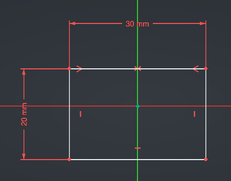
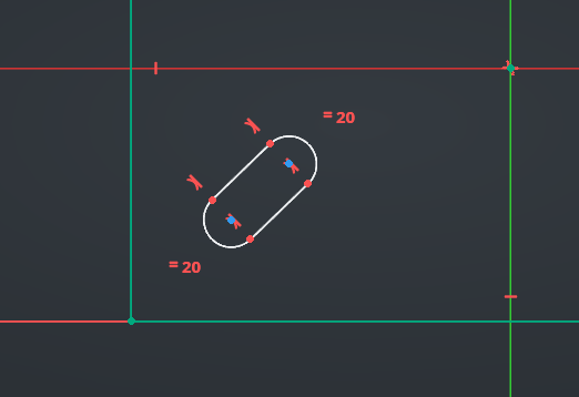
One very useful constraint that might be slightly less intuitive if you come from another software is the Symmetry constraint (keybinding S). You need to select 3 elements for it to work : a first geometry element, then a second, then either a line or a point that will be used as (you guessed it) the symmetry line or point. For example here, select the top-left corner of the rectangle, then Ctrl-click on the top-right corner, then Ctrl-click on the green vertical line (all three should turn blue), then finally press the S key. This will make the rectangle horizontally symmetric around the vertical axis, and the constraint will be shown as little red arrows next to the corresponding elements :
Now, click on that symmetry constraint in the Tasks panel then delete it :
Then, do the same thing again but with the top-left corner, the bottom-right corner, and the origin point. This will ensure your whole rectangle is centered around the origin :
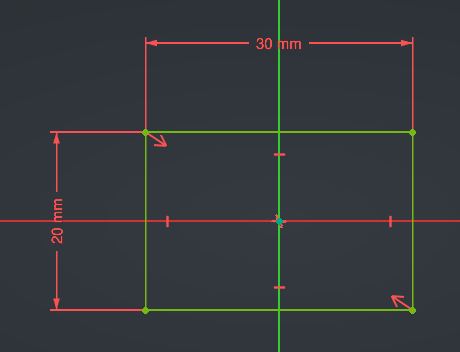
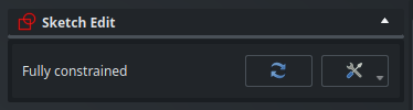
As it happens, the sketch has turned bright green. That means that it is now fully constrained, as said explicitly by the Tasks panel :
This is because there is only exactly one possible way for a 30x20mm rectangle centered on the origin to exist on the plane. There are no degrees of freedom left, everything has an explicit position and dimensions and nothing can move. That’s a good thing. As a rule, always ensure that your sketches are fully constrained when designing parts ! This is important for the stability of your model, as well as to make sure the part you are drawing actually looks like what you intend it to.
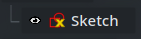
FreeCAD will warn you about under-constrained sketches with a yellow “X” icon in the Tree View :
Construction geometry
Construction geometry refers to geometry elements that can be used to help set up constraints, but should not lead to volumetric features, and therefore will be ignored by the 3D operations that you will apply on your sketch.
Let’s say that we want to add a small slot at 45 degrees in our part, next to the bottom-left corner. We can use the Slot tool (G S) :
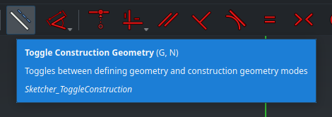
However, how can we enforce the “45 degrees” constraint? One easy way is with a construction line, on which we can assign constraints. While nothing is selected in the 3D view, click on the Toggle Construction Geometry button in the toolbar, or press G N :
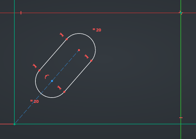
You will see that the buttons of all the primitive shapes turn blue. Now, select the Line tool (G L), draw a line from the bottom-left corner of the rectangle up to the top-right centerpoint of the slot (in both cases, it should “snap” and create a coincident constraint automatically), then constrain the other centerpoint of the slot coincident on this line as well. This should look something like this :
Construction geometry appear in blue, with a dash pattern.
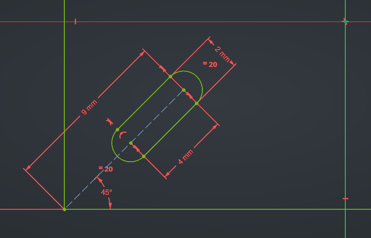
It is now easy to add the angular constraint : select the Dimension tool (D), click on the construction line, then on the bottom line of the rectangle, and type “45”. The length of the line can also be constrained, as well as the other missing dimensions, to obtain a fully-constrained sketch again :
This was only an example — let’s remove this slot to keep the sketch simple before moving forward. Also, click on the Toggle Geometry Construction button again to get back our standard primitive tools.
You can also toggle existing geometry between normal and construction type. Just select some elements and click on the same button button in the toolbar, or press G N. Most of the time, it is actually quicker to draw normal geometry, select it, then convert it to construction with G N, than to toggle the state of the whole toolbar — but that’s obviously up to you.
Transformation functions
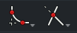
The Sketcher workbench also offers some transformation functions, such as Fillet, Chamfer and Trim Edge. Explore them from the drop-down menus here :
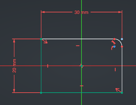
Let’s add a Fillet as an example. Click on the Fillet icon or press G F F on your keyboard, then click on the top-right corner of the rectangle :
The sketch is no longer fully constrained, and consequently the colors have changed. The two bottom-left lines, and their three adjacent points, are now dark green : that means that these elements are still constrained and cannot move. The white lines still have degrees of liberty and can move : this is because we haven’t yet constrained the fillet we just added.
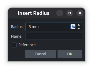
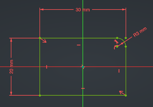
Press D to insert a new Dimension, and click on the arc. Specify its radius (let’s say 3.0mm) and validate :
The sketch is now fully constrained again :
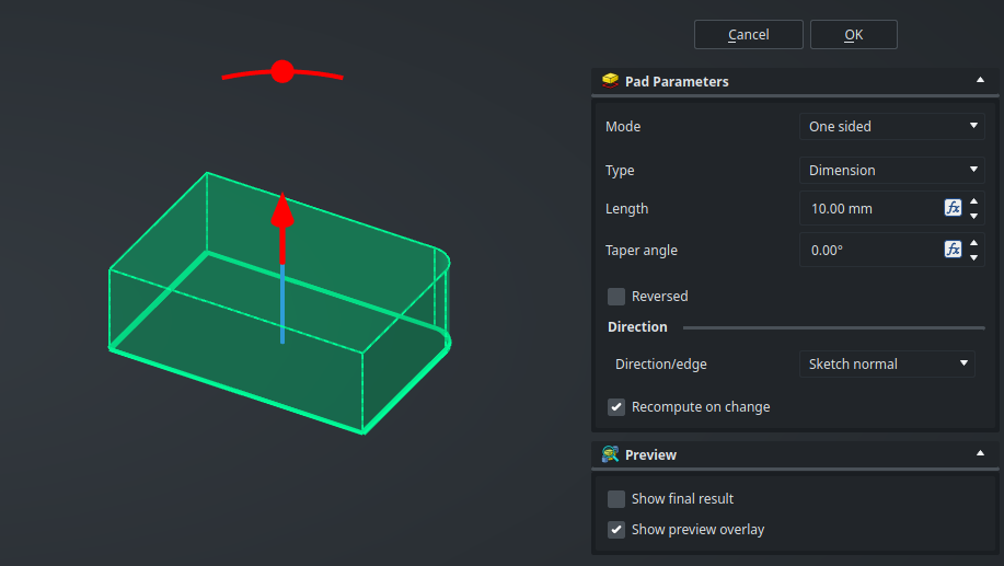
Close the Sketch, then insert a Pad operation to create a volume with it :
Referencing existing geometry
Now that we are familiar with the basic features of the Sketcher workbench, let’s move on to a more advanced use-case : linking elements in our sketch to existing geometry.
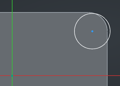
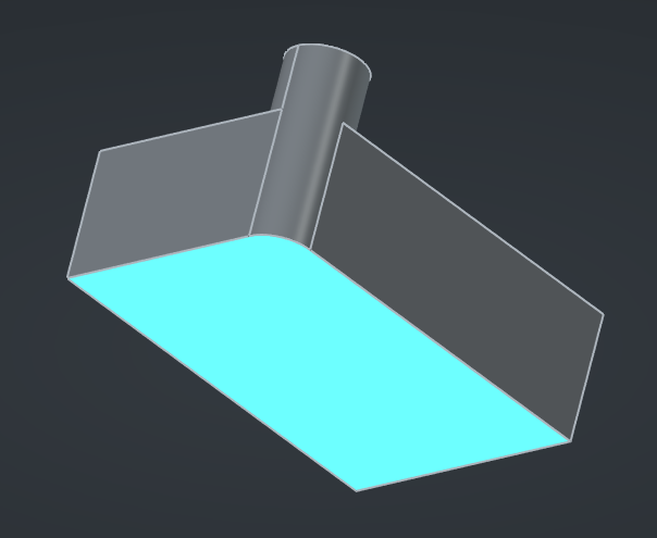
Let’s say we want to add a cylinder extruded on the top-right corner of our part, that perfectly matches the fillet we added in the previous sketch in order to end up with a continuous circular face on the side of the part. This sounds simple enough : we need to create a new sketch on the top face of the body, draw a circle (G C), constrain it on the underlying arc, then add a pad operation.
Do exactly this, up to the constraint step. You might by surprised to see that, unlike the way most other CAD software work, here nothing from the existing geometry seems to highlight or snap :
Dependency, or no dependency ?
Of course, placing the circle by hand more or less at the correct place instead is not an acceptable solution — geometry is math, and math is perfection. Neither is acceptable, you might say, the solution of constraining the circle from scratch (relative to the origin) with position and diameter dimensions : what about if we update the first sketch to change the size of the rectangle or the radius of the fillet? The beauty of parametric design is that this circle should be linked to the fillet, so that it automatically updates accordingly.
Let’s think this through, though. There is one upside with the idea of constraining everything back from the origin and not referencing the fillet : what if we actually decide we don’t want a fillet on the base of the part, and we update the first sketch to reset the corner back to a straight angle ? If we had (somehow) constrained the circle in the current sketch to the underlying fillet, that constraint would then break, and the model would not recompute — we would need to hunt for that broken reference in the feature tree and update it in order to fix our model. However, if we have used only dimensions based on the origin in the second sketch, we can remove the fillet in the first sketch and the model will be fine.
But… maybe that part wouldn’t make sense anyway with that circular extrusion above a straight corner, and having it break is actually preferable, because then we have the opportunity to notice that something is wrong and to fix it, instead of silently computing a geometrically-valid but out-of-spec part.
What I’m getting at is that this, as most things, is a compromise : constraining a sketch on underlying geometry creates dependencies, and dependencies are a design choice. Which is why, while most other CAD packages allow directly snapping on everything in the view and silently create implicit dependencies, FreeCAD follows a more conservative approach and asks you to explicitly specify those dependencies, only where you decide that they make sense. The former is undeniably quicker and “feel” nice to use, but the latter leads to more intentional and robust models.
Projected geometry
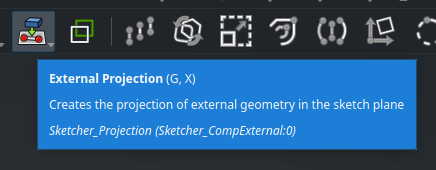
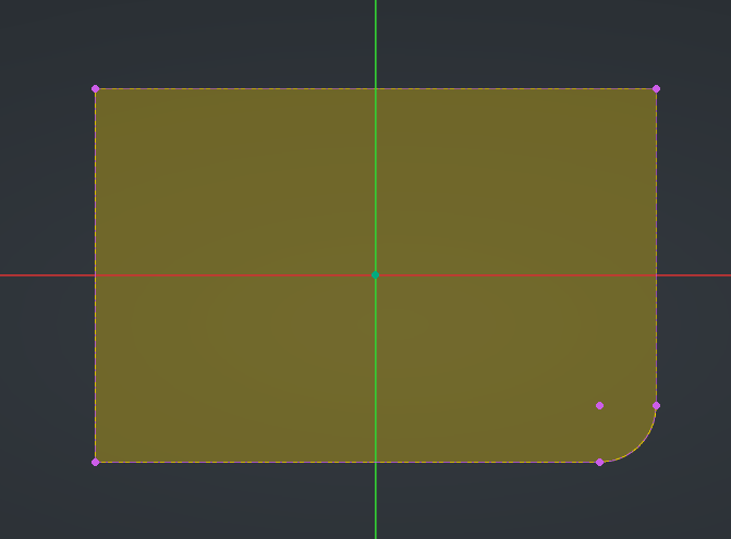
With this bit of tangent out of the way, let’s say that in the case of this part, we decide that removing the fillet later doesn’t make sense, but that we might change its size in the future, so we decide that we do want to constrain the circle on it. We need to use the External Projection tool to, as its name imply, project the arc into our current sketch :
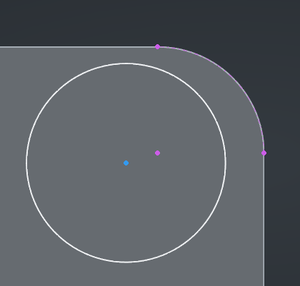
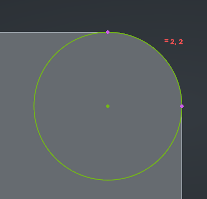
Then hover over the arc and click on it. The arc and its center will appear as a purple construction geometry. The purple color indicates that this is an external reference.
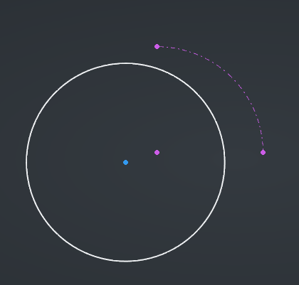
If you have trouble seeing this line, hide the underlying Pad using its visibility icon in the Tree View, this will make things clearer :
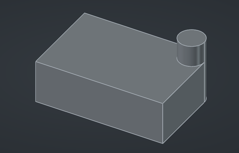
Now, it’s business as usual : we can constrain the center of the circle to the center of the arc with a Coincident constraint, and the radius of the circle to the radius of the arc with an Equal constraint. Our sketch is now fully defined, we can close it and create the pad operation :
When working on sketches with existing geometry all around, by default FreeCAD will automatically clip the model above the sketch plane in order to provide a clear view of your work, which is very handy. However, in case you need to see this geometry (for example in order to project it in the sketch), you can toggle this behavior by right-clicking on the background of the 3D view and selecting Toggle Section View, or by pressing Q S.
Cross-body references
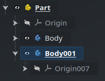
To wrap this post, let’s quickly look at one last use-case. We’ll start by creating a new Body next to the first :
The new Body001 automatically gets activated.
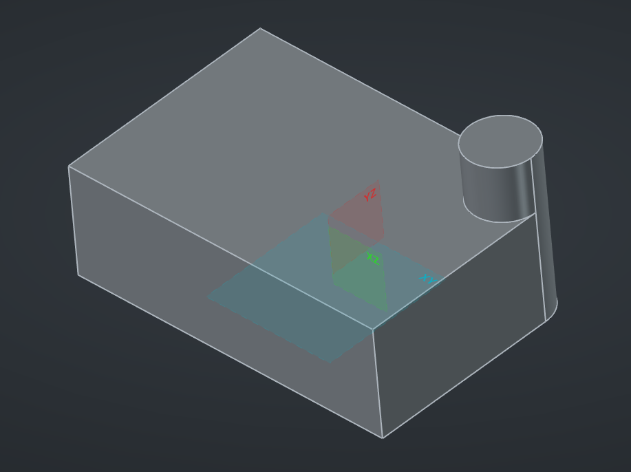
Let’s say that this new Body represents another piece of the same mechanical part, which sits below the first one, and should match the same footprint (so, some kind of support or base). In this new Body, we can therefore create a sketch based on the XY plane :
By default this will show the sketch from the top view, with the current body clipped, but this is not what we want. Instead, using the navigation cube, move to the bottom view :
Select the External Projection tool, like before, and hover over the edges. But… nothing happens. The status bar hints at the reason :
Because two different Bodies are related in a much more “distant” way than two features of the same Body, creating a simple external projection this way would be too brittle. If one body moves, everything may break.
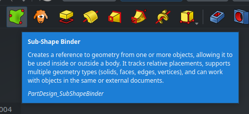
Instead, FreeCAD enforces a more reliable and intentional mechanism for these kinds of cross-Body references, through a dedicated object : a Sub-Shape Binder. A Sub-Shape Binder is an object from the Part Design workbench that can “bind” to and track some geometry elements from some other shape in your document. It can link to entire shapes (like other Bodies), or only some sub-elements of those shape (like a specific set of faces and/or edges of a cube), hence its name.
Along with Sketches and Features, a Body object can also contain Sub-Shape Binder objects. This means that these Binder objects represent a good way to “import” some external geometry into a Body in a parametric way, by acting as a kind of “proxy”. Once that geometry is inside the Body, it can be used in sketches as usual with the External Projection tool. Let’s put it in practice in our example !
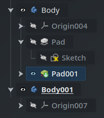
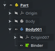
Close this empty sketch, then delete it : since we want to reference the binder from the sketch, we need to create the binder first in the “timeline” of the Body. Rotate the 3D view to see the bottom side of the part, then select the bottom face of the Body object. Make sure that the second body (Body001) is active. The Tree View and the 3D view should look like this, respectively :
Pad001 is selected, Body is active.
Be careful here, this is important : when creating a Sub-Shape Binder, it will be created inside the active Body, and link to the selected geometry. Here, we want to create it inside Body001, and link to the selected bottom face of Body, so the Tree View looks good with Body001 active and the selection inside Body.
Note that in the Tree View, FreeCAD selects the “narrowest” object that relates to the selection from the 3D view, which in this case is actually the last Feature object of the Body instead of the Body itself. This is perfectly fine.
Now, click on the icon with the green squiggly shape in the toolbar to create the Sub-Shape Binder :
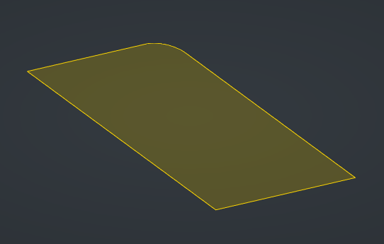
Clear the selection from the 3D view. You will see that the bottom face has now taken a yellow tint : this is the Sub-Shape Binder displayed above the face of the Body. Hide the Body object to view only the Binder :
Since the geometry created by this Binder is a face and is inside the Body, we can use it directly as the support for the sketch. Select the face in the 3D view and create a new sketch. Now, we will be able to use the External Projection tool to reference some elements in our sketch to the Binder, and through it, to the face of the first Body :
A Sub-Shape Binder is able to link to geometry from other documents as well. This is one way to connect parts from different documents together (the other way is with a Link, which we’ll cover in a later post). The process is exactly the same : activate the Body into which the Binder should be created in the parent document, switch to the child document using the tab bar at the bottom of the screen, select the target geometry you want to bind to, switch back to the tab of the parent document, and finally create the Sub-Shape Binder using the button in the toolbar.
However, remember that since FreeCAD will link the two documents based on their respective file names, both must have been saved to disk at least once in order for the Binder to work. Obviously, if you rename the files, you will need to fix the binding manually afterwards.
If you want to add some geometry to an existing Binder, the process is pretty easy : first select some other elements in the 3D view, then come back to the Tree View. Hover over one of the objects that have the blue halo indicating that they are selected, then drag-and-drop it into the Binder (you can also use the T D keybinding to initiate the drag-and-drop operation directly — think “Tree Drag“). The selected geometry will be added to the Binder. If you want to entirely replace the content of the Binder with that new selection, just hold Ctrl while doing the drag-and-drop. There isn’t currently (to my knowledge) a way to selectively remove an element from a Binder.
Binders have a handful of interesting properties under the Offsetting group that can be used to apply an offset (positive or negative) relative to the underlying geometry.
Besides the Sketcher workbench, FreeCAD also offers a wide range of tools that you can use to draw 2D or even 3D profiles under the Draft workbench. In case you are looking for a Text primitive to emboss some words on a part for instance, this is where you will find it. We won’t cover this workbench in this article, but I encourage you to explore it and see all it has to offer.
That’s all regarding sketches ! Today’s post was a bit longer than the previous one, but you now have all the tools you need in order to draw complex and stable parts that reference each other the way you intend them to. Next time, we’ll learn how to move Parts and Bodies and how to attach them to each other in a parametric way, as well as a few other tips and tricks. Until then, have a good one !